Floating diffused air aerator

a technology of diffused air and aerator, which is applied in the field of aerators, can solve the problems of high energy consumption, high maintenance cost, and high energy cost, and achieve the effect of conserving energy inputs

Inactive Publication Date: 2009-04-21
HALDANE WILLIAM J
View PDF18 Cites 14 Cited by
  • Summary
  • Abstract
  • Description
  • Claims
  • Application Information

AI Technical Summary

Benefits of technology

[0011]The present invention seeks to provide an aerated lagoon system using a reduced or low pressure, air-lift pump assisted method of aeration with radially divergent discharge. The present invention provides a new, useful and nonobvious means to mechanically provide oxygen to and circulate a body of liquid. The present invention mechanically provides 100% of the oxygen requirement for various waste load demands, and is thus not dependent on natural reaeration technology. If, however, a lagoon is benefitting from natural aeration, then the present invention's variable speed blower drive may be adjusted to conserve energy inputs. These and other features of the present invention allow it to optimize the performance of a body of liquid such as a waste water lagoon or pond.

Problems solved by technology

Many of these living organisms, such as aerobic bacteria, require oxygen to survive, but are immobile.
Pumping great quantities of oxygen-containing gas to the depths of a body of liquid requires great energy, and thus monetary expenditures.
All of these devices are accepted methods of oxygen transfer, and all have inherent disadvantages, including high energy costs, high maintenance costs, inconsistent oxygen transfer rates and turbulent discharges which result in flow interference and small zones of influence.
Effluent (facility discharge) quality requirements are becoming more restrictive, requiring more efficient technologies for successful operation.
The continually increasing cost of power puts new pressure on industry to find more efficient treatment processes and equipment.
Past developments in the art have attempted to circulate waste water but have done so at high energy costs.
Other devices, more recently introduced have sought to lower energy costs but have not been successful because they cannot provide oxygen transfer ratings accepted by industry and government.
No device to date has successfully circulated liquid in a non-turbulent manner in order to maximize flow and maximize oxygen transfer.
As mentioned above, the disadvantage of these systems is a lack of industry-accepted, measured oxygen transfer rates, and their restriction to bodies of liquid with low waste loads.
In addition, natural reaeration cannot serve as a primary manner of predictably treating waste water because anomalies in waste can inhibit natural reaeration (e.g. oil slicks caused by petroleum or vegetable oils, and ice in cold winter climates).
None of the aerated lagoon systems use a low pressure, air-lift pump assisted method of aeration with radially divergent discharge.

Method used


Image

  • Floating diffused air aerator
  • Floating diffused air aerator
  • Floating diffused air aerator

Examples


Embodiment Construction

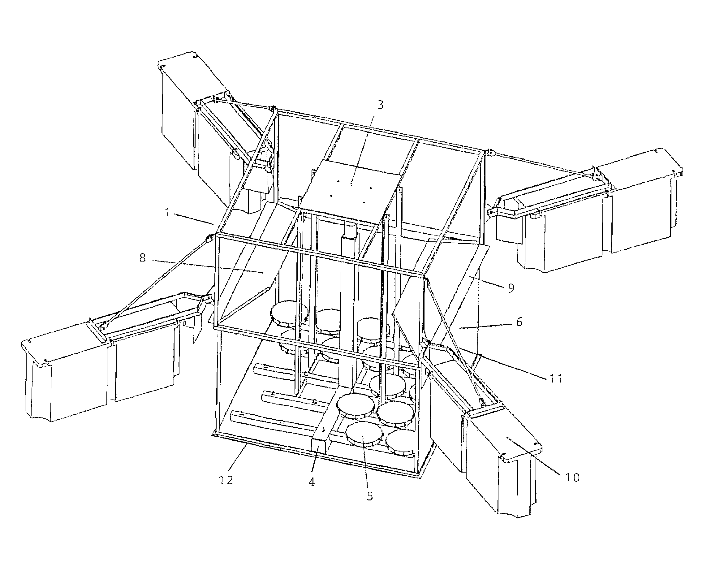
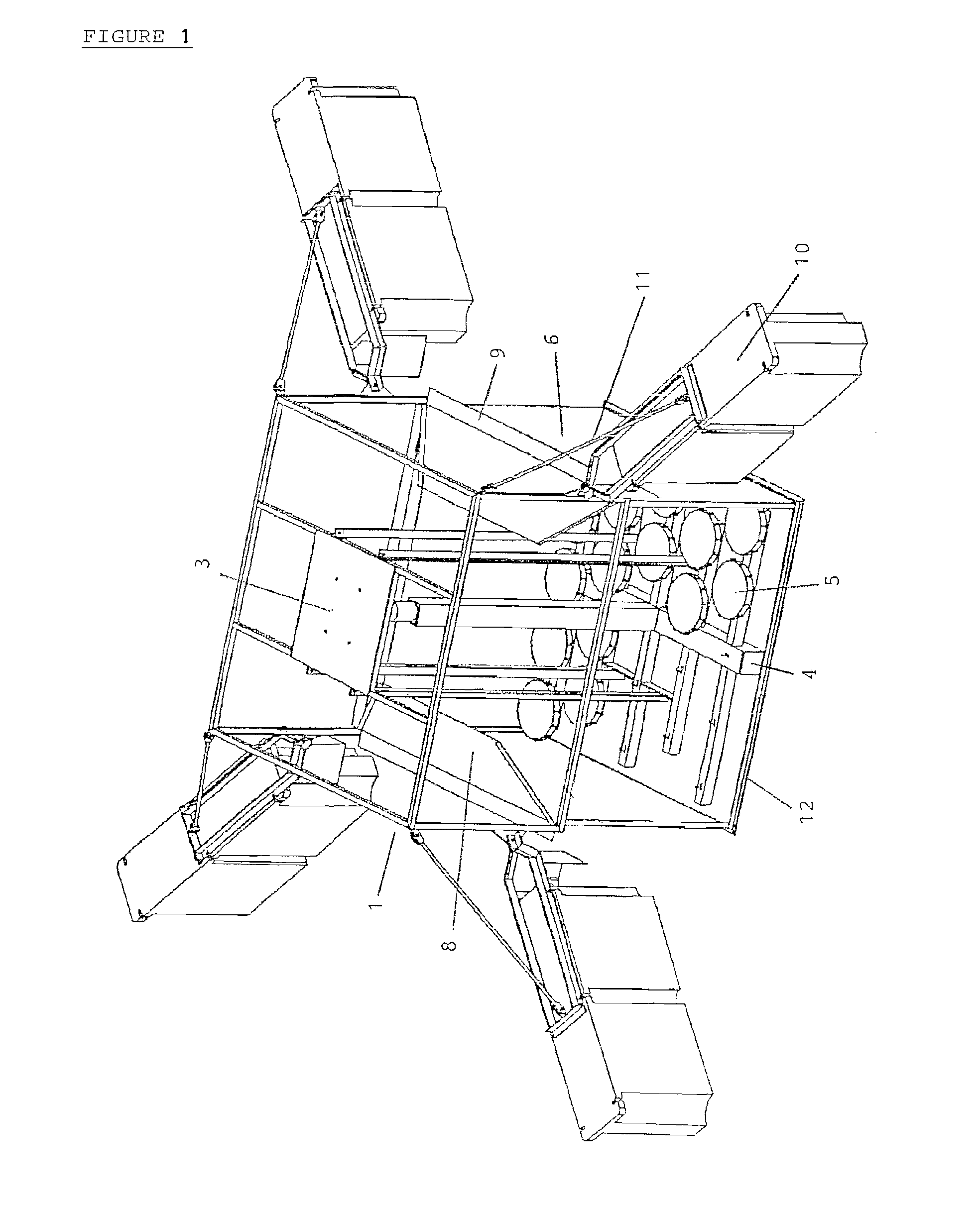
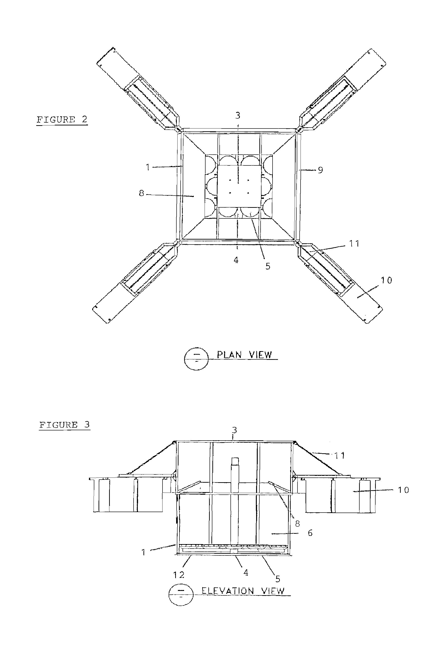
[0038]The primary objective of the present invention is to provide an adaptable aeration device for oxygenating and circulating a liquid such as waste water in ponds, lagoons and similar bodies of liquid using diffused aeration technology.

[0039]It is an additional objective of the floating diffused air aerator to provide a method to sufficiently increase the dissolved oxygen content of waste liquid by introducing oxygen-containing gas into the body of fluid. In a further objective for the aerator, the aerator provides a method to produce a low turbulence, near laminar flow projecting radially outward from the aerator. Simply put, the present invention seeks to efficiently get bubbles into a body of liquid and then get them out in order to induce optimum flow. In another objective, the aerator seeks to provide a method to take advantage of the natural re-aeration processes which occur due to the increased circulation. In a further objective, the aerator seeks to provide a method to a...


PUM

PropertyMeasurementUnit
diameteraaaaaaaaaa
thicknessaaaaaaaaaa
angleaaaaaaaaaa

Abstract

An aerator for mechanically inducing near laminar flow and controlled turbulence in a liquid waste treatment lagoon or pond. A blower, blower mount platform, diffuser modules, aeration manifold, aeration chamber, an adjustable, telescoping aeration chamber extension, baffles, and buoyancy apparatuses attach to a frame. The diffusers are located beneath the surface of the body of liquid at a predetermined, fixed depth. The blower supplies air to the diffusers and liquid-bubble mixture is released into an aeration chamber where artificial aeration is maximized. The mixture then rises through the aeration chamber. Bubble dissipation and flow conditioning baffles force bubbles to coalesce and vertically dissipate into the atmosphere. The liquid flows over the top of the baffles and a flow manipulation rim to radiate outward and parallel to the pond surface with minimum turbulence at an optimum flow discharge rate. The aerator provides optimized oxygen transfer at low energy costs.

Description

CROSS REFERENCE TO RELATED APPLICATION[0001]This patent application claims priority under 35 U.S.C. § 119(e) to U.S. Patent Application Ser. No. 60 / 512,309, entitled “Floating Diffused Air Device”, and filed on Oct. 18, 2003. The entire disclosure of that provisional patent application is hereby incorporated by reference.FIELD OF THE INVENTION[0002]The present invention generally relates to an aerator designed to affect a body of liquid, using diffused aeration technology applied from an isolated apparatus movably-supported by buoyancy apparatuses. The aerator according to the present invention is contemplated to be used in any of a variety of operations including personal, public, industrial, agricultural or aquacultural. Said body of liquid may comprise waste water, a pond, a lagoon, a basin, a lake, a stream or a similar body of liquid.BACKGROUND OF RELATED ART[0003]It is well established that oxygen and circulation are among the key components of any healthy, water-based ecosyst...

Claims


Application Information

Patent Timeline
Patent Type & Authority Patents(United States)
IPC IPC(8): B01F3/04
CPCB01F3/0412B01F13/0049B01F2003/04148B01F2003/0417B01F2003/04234B01F2003/04297Y10S261/70B01F23/2311B01F23/231142B01F23/23113B01F23/23116B01F23/231262B01F33/503
Inventor HALDANE, WILLIAM J.
Owner HALDANE WILLIAM J
Why Eureka
Try Eureka