
Device for precise chemical delivery and solution preparation

a technology of precise chemical delivery and solution preparation, applied in the field of devices and methods for forming solutions, can solve the problems of difficult adjustment of sub-l air volumes accurately and precisely, and difficulty in dislodging nl-size droplets from pipette tips, etc., and achieves little human control

Inactive Publication Date: 2009-04-21
CASE WESTERN RESERVE UNIV
View PDF6 Cites 9 Cited by
  • Summary
  • Abstract
  • Description
  • Claims
  • Application Information

AI Technical Summary

Benefits of technology

[0017]An advantage of at least one embodiment of the present invention is that non-volumetric (non-convective) reagent delivery is used for transfer of chemicals. As a result, substantially no volume changes are induced in the target solution.
[0033]Another advantage of at least one embodiment of the present invention is that it enables delivery to be achieved without moving mechanical parts.

Problems solved by technology

While such novel pipette and burette designs reach into the μL volume ranges, the mechanical working principles do not facilitate their adaptation to the handling of even smaller target liquid volumes or smaller reagent increments delivered.
Adjusting sub-μL air volumes accurately and precisely is also difficult.
Moreover, dislodging a nL-size droplet from a pipette tip is often difficult, since capillary forces become stronger relative to droplet mass as the droplet size decreases.
Thus, accuracy and precision for the delivery of sub-μL volumes by a pipette based on air displacement is not readily achieved.
Furthermore, preparation of solutions of relatively low concentrations often involves multiple steps that are difficult to perform with high final accuracy and precision.
This, often tiny, amount of material may be hygroscopic (i.e., it absorbs water from humidity in air).
This tends to falsify the weighed amount.
Additionally, a powdery material may tend to float in air, contaminating the balance and the environment.
The chemical may also be hazardous, posing problems to the user.
These steps, requiring utmost care, are often sources of significant errors that propagate through all subsequent steps.
Further errors tend to be added in each step.
In addition, such a procedure is labor intensive and prone to mistakes.
Moreover, the process of serial dilution frequently uses far more of the raw material than is needed in the final solution than is needed, resulting in wastage of often expensive materials or hazardous waste production.
The mechanized burettes suffer similar drawbacks when sub-μL volumes are to be delivered in a continuous fashion.
Accuracy and precision of the displaced reagent volume become worse as the delivered volume decreases, especially in the nL volume range.
Parasitic diffusion between the burette tip and the target liquid may add errors that are difficult to estimate, and even more difficult to correct.

Method used


Image

  • Device for precise chemical delivery and solution preparation
  • Device for precise chemical delivery and solution preparation
  • Device for precise chemical delivery and solution preparation

Examples


example 1

Preparation of a Ferricyanide Delivery Burette

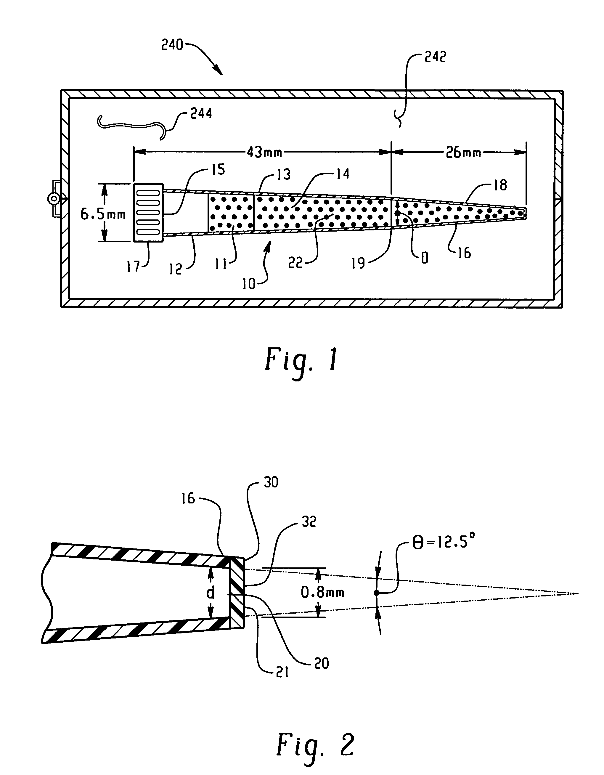
[0205]Ten mL of an aqueous solution containing 3.29 g of K3[Fe(CN)6](P-3667 Sigma) and 74.6 mg of KCl (P217-500, Fisher Scientific) was prepared. To this solution, 0.5 g of a gelling agent, agarose (A-6013, Type 1: Low EEO [9012-36-6], Sigma) was added. This mixture was heated up to 80° C. until the solution becomes clear. One mL of this solution was filled into a micropipette tip (101-1000 μL, 2 13 / 16 inches, Eppendorf style, 21-375E, Fisher Scientific) and allowed to stand at room temperature until the filling solution became gel. The detailed dimensions of the thus prepared ferricyanide delivery burette are shown in FIG. 24.

example 2

Preparation of a Potassium Delivery Burette

[0206]Ten mL of an aqueous solution containing 74.6 mg of KCl (P217-500, Fisher Scientific) 5.84 mg of NaCl (S-9625, Sigma) and was prepared. To this solution, 0.5 g of agarose (A-6013, Type 1: Low EEO [9012-36-6], Sigma) was added. This mixture was heated up to 80° C. until the solution becomes clear. 200 μl of this solution was filled into a micropipette tip (1-200 μL, 1⅞ inches, Eppendorf style, 21-375D, Fisher Scientific) and allowed to stand at room temperature until the filling solution became gel.

example 3

Ferricyanide Delivery

[0207]A ferricyanide burette was prepared as for Example 1. FIG. 20 shows the experimental setup for ferricyanide (and potassium) ion delivery. 200 μL of 0.1M KCl aqueous solution was used as a sample (target) solution 50. The solution 50 was placed in a container having a silicone elastomer liquid support surface. To monitor the delivered ferricyanide concentration into this sample solution, a micro Pt electrode 250 8 μm in diameter was used in combination with a counter electrode 252 formed from stainless steel wire and a reference electrode 254 (BAS Ag / AgCl microreference electrode). The cyclic voltammograms for various delivery times from 0 to 41.3 minutes are shown in FIG. 21. The current due to reduction or rather, electro-reduction of ferricyanide increases with increasing delivery time, indicating successful reagent delivery with the prepared diffusional burette 10. FIG. 22 shows three sets of the ferricyanide delivery results obtained by using the same ...


PUM


Abstract

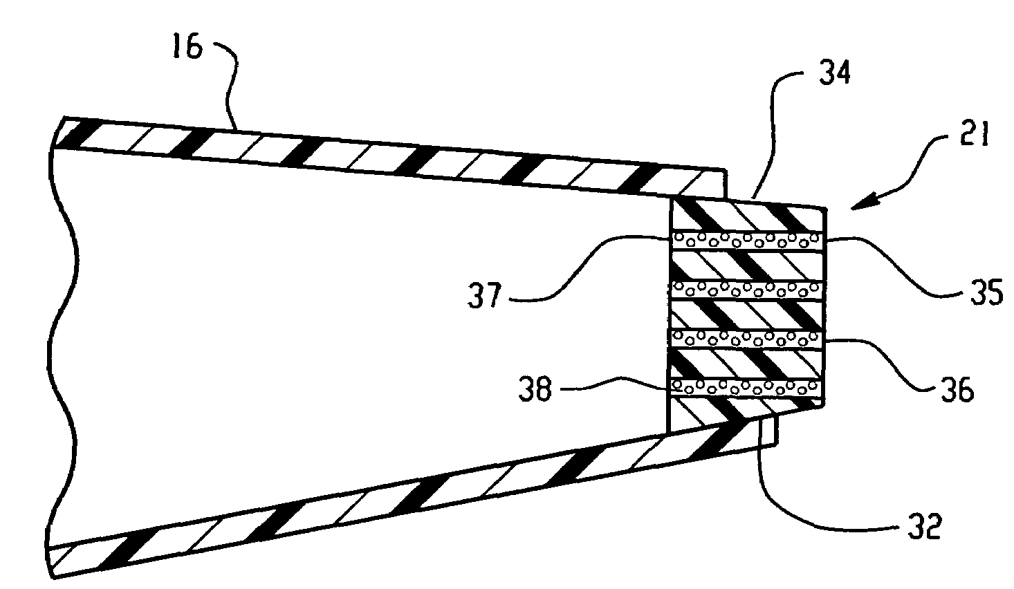
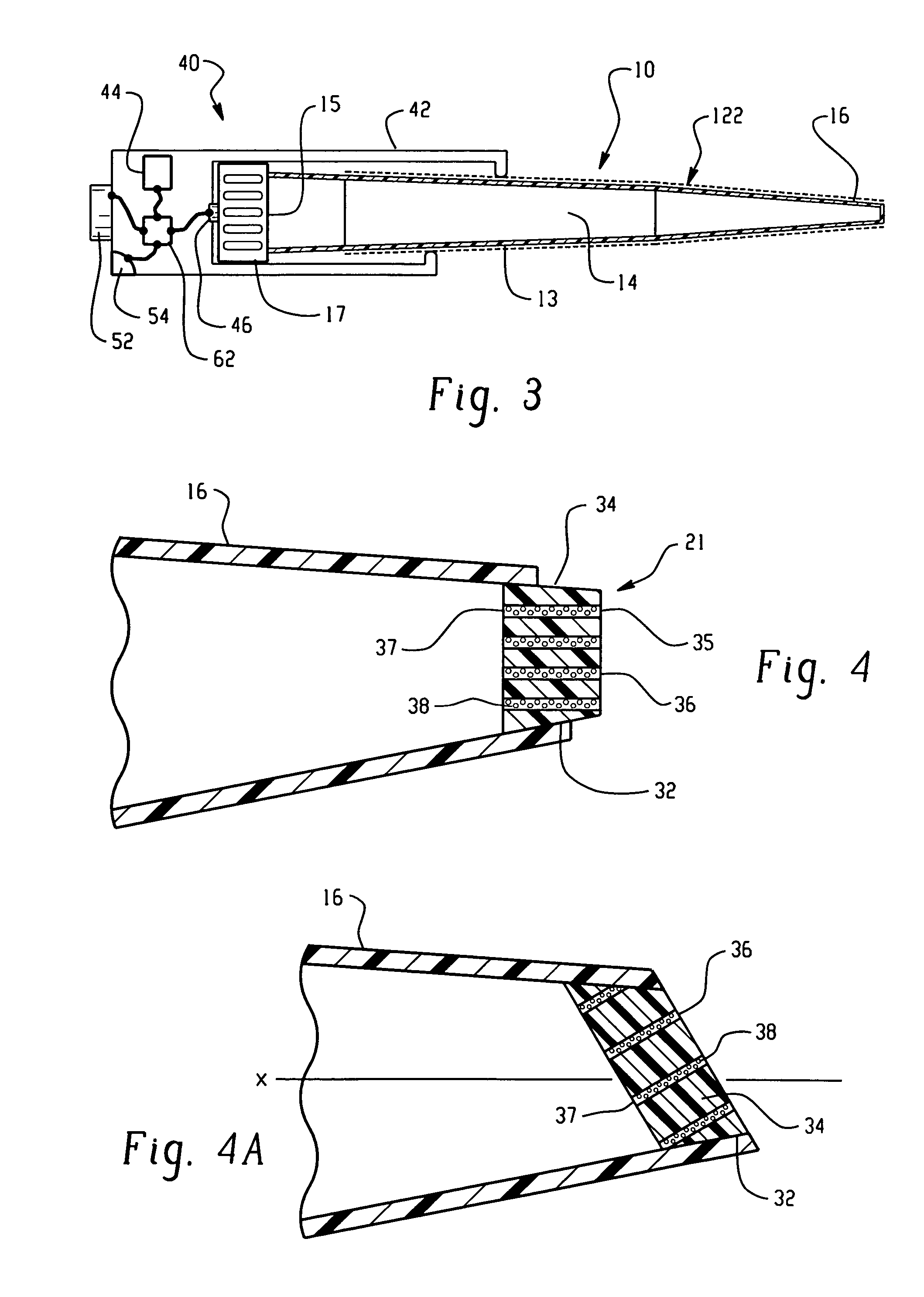
A burette (10, 110, 200) suitable for delivery of a reagent into a target solution (50) employs diffusion for delivering the reagent. The reagent is in the form of a solution, which is combined with a matrix material (22), such as a gel or porous ceramic. A membrane (32) covers a delivery outlet (20) to the burette. In one embodiment, the delivery outlet comprises a plurality of fine bores (36), each one filled with or covered by a membrane (38). Stirring of the burette or target solution is achieved with a stirring means (104, 106). A heating or cooling means (80) heats a tip (16) of the burette.

Description

[0001]This application claims the benefit of U.S. Provisional Application Ser. No. 60 / 417,149, filed Oct. 9, 2002, U.S. Provisional Application 60 / 460,082, filed on Apr. 3, 2003, and is a continuation-in-part of U.S. patent application Ser. No. 09 / 980,089, filed on Jun. 26, 2003 now abandoned, and claims the benefit of PCT Application Serial No. PCT / US00 / 14805, filed May 30, 2000, and U.S. Provisional Application Ser. No. 60 / 137,134, filed May 28, 1999, from which U.S. patent application Ser. No. 09 / 980,089 claims priority, the specifications of all of which are incorporated herein in their entireties, by reference.BACKGROUND OF THE INVENTION[0002]1. Field of the Invention[0003]The invention relates to a device and method for forming solutions. In particular, it relates to a diffusional burette for controlled delivery of chemicals and biochemicals into a target material, such as a liquid, and will be described with particular reference thereto.[0004]2. Discussion of the Art[0005]Cur...

Claims


Application Information

Patent Timeline
IPC IPC(8): B01L3/02B01L99/00G01N31/16G01N33/487G01N35/10
CPCB01L3/0275B01L3/0293B01L2300/0681Y10T436/2575G01N31/16G01N2035/1053B01L2300/18
Inventor GRATZL, MIKLOSTOHDA, KOJIROZAKIS, GEORGE
Owner CASE WESTERN RESERVE UNIV
Learn More