Laser-assisted coating removal method

a laser beam and coating technology, applied in the direction of chemistry apparatus and processes, manufacturing tools, welding/soldering/cutting articles, etc., can solve the problems of reducing the quality, quantity of material removed, time-consuming and labor-intensive remediation, etc., to facilitate the precise positioning of the laser beam and increase the treatment outlay

Inactive Publication Date: 2009-04-28
AIRBUS OPERATIONS GMBH
View PDF29 Cites 29 Cited by
  • Summary
  • Abstract
  • Description
  • Claims
  • Application Information

AI Technical Summary

Benefits of technology

[0006]The laser may advantageously be used only on the area to be stripped. The coherency properties of the laser and the essentially parallel beam progression of the laser beam may make it possible to traverse an area on the surface with a high level of precision. As a result of the pulsating operation of the laser, exposure to laser energy can be kept brief, and it is believed that no undesired temperature change of the basic material is brought about. This brief time can be sufficient to evaporate the surface coating without excessively heating the underlying carrier material in the process. Negative effects caused by exposure of the carrier material to heat may thereby be avoided or minimized.
[0019]The laser may be adapted for generating a laser beam with a power ranging from 50 W to 4 kW, in particular with a power ranging from 100 W to 4 kW, and further in particular with a power ranging from 120 W to 4 kW. As a result, the laser economizes on power, making it efficient to use. The device may further comprise a wavelength adjuster 27, which allows the wavelength to be tuned to the material to be removed. By adjusting the wavelength to the absorption behavior of a surface coating, the coating selectively absorbs the energy conveyed by the laser beam in the area covered by the laser and is removed from the surface. As a result, non-conductive coatings may be remediated in an advantageous manner, such as by evaporation, separation or conversion to a conductive material.

Problems solved by technology

However, remediation is time-consuming, man power intensive and inefficient.
In addition to the high cost involved, remediation reduces, the quality, i.e., the quantity of material removed, and in a poor surface quality (roughness), which detracts from electrical conductivity and / or increases potential for corrosion.

Method used


Image

  • Laser-assisted coating removal method
  • Laser-assisted coating removal method
  • Laser-assisted coating removal method

Examples


Embodiment Construction

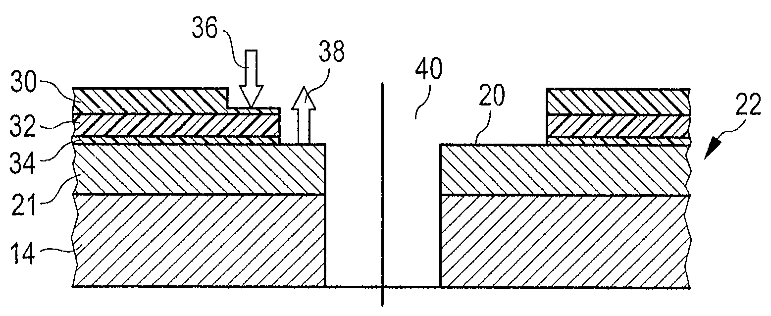
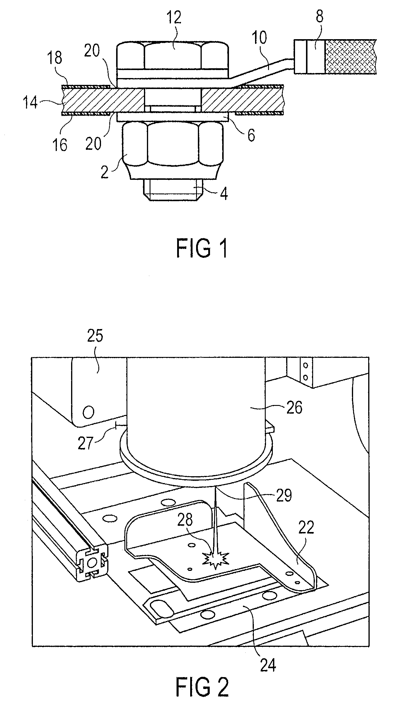
[0029]FIG. 1 is a diagrammatic sketch of a chassis terminal surface connected with an electrical cable. The figure shows a conductive basic material 14, which can be plated or unplated. Structural elements comprised of a conductive basic material 14, e.g., an aluminum alloy like Al 2024, are often used in aircraft construction. A non-conductive surface protection system 18 is applied to this conductive basic material 14. This non-conductive surface protection system 18 protects the basic material 14 against outside influences, e.g., in order to impede corrosion. The non-conductive surface protection system 18 can be composed of an anodized layer based on chromic acid or sulfuric acid, of primer and topcoat paint, wherein it is not necessary that all layers be used at the same time, or any other system known in the art.

[0030]FIG. 1 shows an example for the chassis terminal of part of an airplane. The conductive surface 20 of the part is connected by a connecting cable 8 and terminal ...


PUM

PropertyMeasurementUnit
poweraaaaaaaaaa
poweraaaaaaaaaa
poweraaaaaaaaaa

Abstract

Stripping is accomplished with a pulsed laser beam that targets the material and area to be stripped. The wavelength laser beam may be selected or adjusted to the absorption behavior of the material to be stripped without damaging the underlying base material. A control unit may operably adjust an optical system to guide the laser beam over the surface to be treated. a coating. This makes it possible to improve the surface stripping process.

Description

RELATED APPLICATIONS[0001]This application claims the benefit of Provisional Application No. 60 / 600,063, filed Aug. 9, 2004, German application 10 2004 025 017.0, filed May 18, 2004 and European Patent application 05 002 293.8, filed Feb. 3, 2005.FIELD OF THE INVENTION[0002]The present invention relates to the removal of coatings from surfaces. In particular, the present invention relates to a method for removing a surface coating on a surface by means of a laser, as well as to a cleaning device and a corresponding use.TECHNOLOGICAL BACKGROUND[0003]Airplanes are constructed in such a way that electrostatic charges do not cause electrical systems to become damaged or malfunction. In like manner, electrostatic charges must not produce any damage to structures comprising the aircraft framework components or aircraft skin. A good electrical conductivity of the structure and equipment parts dissipates electrical charges and establishes a good electrical ground connection for the electric...

Claims


Application Information

Patent Timeline
Patent Type & Authority Patents(United States)
IPC IPC(8): B23K26/36B08B7/00B23K26/40
CPCB08B7/0042B23K26/365B23K26/402B23K26/4095B23K2203/10B23K26/40B23K26/361B23K2101/35B23K2103/10B23K2103/50
Inventor ENGLER, HARALDHOENEMANN, LOTHAR-BERNHARDDOERR, TILLMANN
Owner AIRBUS OPERATIONS GMBH
Why Eureka
Try Eureka