Linearly regulated battery charger

a battery charger and linear regulation technology, applied in the field of battery chargers, can solve the problems of presenting unwanted load to the other power input or the battery in a discharge mod

Active Publication Date: 2009-04-28
IP GEM GRP LLC
View PDF40 Cites 52 Cited by
  • Summary
  • Abstract
  • Description
  • Claims
  • Application Information

AI Technical Summary

Benefits of technology

[0011]In one embodiment, optional bypass transistors (e.g., P-channel MOSFETs or switches) are coupled across the respective OR-ing diodes (or isolation diodes) to selectively provide low impedance paths from the respective power inputs to the system power terminal. The bypass transistors effectively reduce the voltage drops across the respective isolation diodes when activated. Reducing the voltage drops across the isolation diodes ensures that there is adequate voltage to effectively charge the battery even on a low side of the power input regulation band. When the battery is in the discharge mode, the bypass transistors are turned off to prevent battery current from flowing to the power inputs.
[0012]Power may be available from both the primary power source and the secondary power source at the same time. In one embodiment, the dual source selector automatically disconnects the secondary power source from the system power terminal when power is available from the primary power source. For example, if the AC adapter is active while the USB power interface is enabled, the AC adapter provides power to the system power terminal and an overriding circuit shuts off any bypass transistors associated with the USB power interface to prevent reverse current from flowing to the USB power interface.
[0013]In one embodiment, a bi-directional device (or a pass element) in the battery controller couples a positive battery terminal to the system power terminal. The bi-directional device conducts a charging current in a first direction from the system power terminal to the positive battery terminal during charging of the battery and conducts a discharging current in a second direction from the positive battery terminal to the system power terminal during discharging of the battery (e.g., when the battery is providing power to the system load). The bi-directional device advantageously isolates the battery from the system load in the charge mode and provides a low-impedance path from the battery to the system load in the discharge mode. The bi-directional device can fully disconnect the battery from the system power terminal during the sleep mode.
[0020]In another embodiment, the bi-directional device is a P-channel MOSFET with a configurable body contact. The configurable body contact is coupled to the system power terminal during a battery charge mode and coupled to a battery terminal during a battery discharge mode. In one embodiment, a comparator senses a voltage polarity across the source-drain terminals of the P-channel MOSFET to connect the body contact accordingly. The configurable body contact serves as a reference for the pass element driver. With the body contact connected to the source-drain terminal with a relatively higher voltage, the pass element driver can stop current from flowing in either direction through the bi-directional device by driving its gate voltage to logic high, thereby fully disconnecting the battery form the system power terminal. In one embodiment, a switching diode can be coupled across the P-channel MOSFET to assist in a transient response of the battery if a full disconnection from the system power terminal is not required.
[0022]In one embodiment, a current limiting circuit is coupled between the USB power interface and the second input to ensure that the current supplied by the USB power interface does not exceed a predetermined level. The current limiting circuit helps to provide full USB current compliance even if current to the system load exceeds the specified limit of the USB power interface.

Problems solved by technology

Furthermore, if either power input is shorted to ground, the OR-ing diodes serve as isolation circuits that block current flow in a reverse direction from the system power terminal to the shorted power input, which would present an unwanted load to the other power input or the battery in a discharge mode.

Method used


Image

  • Linearly regulated battery charger
  • Linearly regulated battery charger
  • Linearly regulated battery charger

Examples


Embodiment Construction

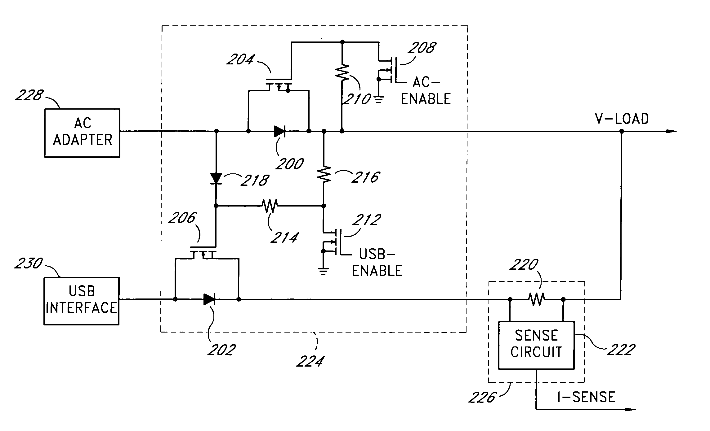
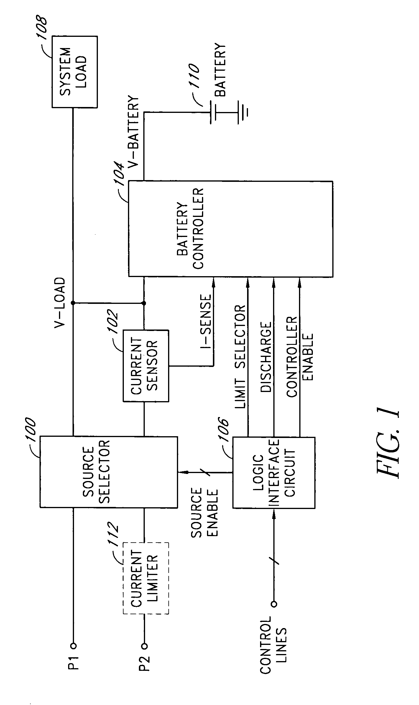
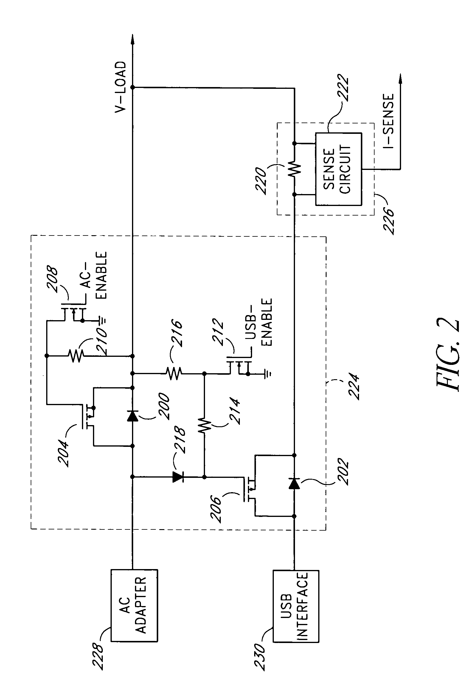
[0029]Embodiments of the present invention will be described hereinafter with reference to the drawings. FIG. 1 illustrates a block diagram of one embodiment of a battery charger. The battery charger includes a source selector 100, a current sensor 102 and a battery controller 104. The source selector 100 selectively couples either a primary power source (P1) or a secondary power source (P2) to a system power terminal (V-LOAD). The system power terminal provides a load current to a system load 108. In one embodiment, the voltage at the system power terminal is a relatively low DC voltage (e.g., 5 volts DC) and the system load 108 is a portable electronic device (e.g., a USB device).

[0030]In one embodiment, the secondary power source (e.g., a USB power interface or port) can supply a limited amount of current and an optional current limiter 112 is inserted between the secondary power source and an input to the source selector 100 to clamp the supply current from the secondary power s...


PUM


Abstract

A battery charger for an electronic device receives current limited power from an external power source, such as a Universal Serial Bus power interface. The battery charger can linearly regulate a charging current to an internal battery and limit the charging current so as not to demand current in excess of what the external power source can provide. A bi-directional pass element coupled between a system power terminal and the internal battery controls the charging current and effectively isolates the internal battery from a system load during charging of the battery while providing a low impedance path from the internal battery to the system load during discharging of the battery.

Description

CLAIM FOR PRIORITY[0001]This application claims the benefit of priority under 35 U.S.C. § 119(e) of U.S. Provisional Application No. 60 / 441,715, filed on Jan. 21, 2003, and entitled USB BATTERY CHARGER, the entirety of which is incorporated herein by reference.BACKGROUND OF THE INVENTION[0002]1. Field of the Invention[0003]The present invention relates generally to battery chargers and more particularly to a battery charger that receives power from a limited power source, such as a Universal Serial Bus (USB) power interface.[0004]2. Description of the Related Art[0005]Many electronic devices operate with a low direct current (DC) voltage supply such as, for example, 5 volts DC. The DC voltage supply may be derived from an alternating current (AC) adapter (e.g., by transforming, rectification and filtering of an AC voltage), or it may be supplied by one or more internal batteries of the electronic devices. Often, such a device obtains DC power from the AC adapter when the AC adapter ...

Claims


Application Information

Patent Timeline
Patent Type & Authority Patents(United States)
IPC IPC(8): H02J7/06
CPCH02J7/0021H02J7/045H02J2007/006H02J2207/30H02J7/04H02J7/0047H02J7/007182
Inventor FERGUSON, BRUCE R.
Owner IP GEM GRP LLC
Why Eureka
Try Eureka