Rotor coupling having insulated structure

a technology of insulating structure and coupling, which is applied in the direction of couplings, superimposed coating processes, machines/engines, etc., can solve the problems that the simple use of grounding electrodes b>9/b> has not been a sufficient countermeasure, and achieve the effect of improving adheren

Inactive Publication Date: 2009-05-12
MITSUBISHI HITACHIPOWER SYST LTD
View PDF16 Cites 17 Cited by
  • Summary
  • Abstract
  • Description
  • Claims
  • Application Information

AI Technical Summary

Benefits of technology

[0012]The present invention was conceived in view of the above-described circumstances and has as its objective the provision a rotor coupling having insulated structure that can assuredly prevent galvanic corrosion of rotors, bearing members and the like caused by shaft voltage in a shaft system that requires insulation and a design in which a generator is disposed in between a steam turbine and a gas turbine or a rotating machinery such as another steam turbine.
[0015]In the rotor coupling having insulated structure according to the first aspect of the present invention, by contacting a ground via the first and second grounding electrodes, the potential of each rotor can be reduced. Furthermore, in this rotor coupling having insulated structure, it is possible to stop the flow of current from the generator rotor to the first grounding electrode. Thus it is possible to offer a design that is an effective countermeasure to the shaft voltage, and therefore, it can prevent galvanic corrosion of bearing members, rotors and the like which is caused by the shaft voltage.
[0017]In the rotor coupling having insulated structure according to the second aspect described above, the galvanization between the generator-side flange and the steam turbine-side flange can be interrupted by the insulating parts. As a result, current flowing from the generator rotor to the first grounding electrode can be prevented.
[0019]In the rotor coupling having insulated structure according to the third aspect described above, very fine pores generated in the alumina layer of the alumina flame coated layer can be covered with silicon resin, improving the electrical insulating effect of the alumina flame coated layer.
[0021]In the rotor coupling having insulated structure according to the fourth aspect as described above, it is possible to improve the adherence to the surface where alumina flame coating is performed by performing the alumina flame coating on top of an undercoat consisting of nickel chrome. Thus, peeling of the alumina flame coating does not readily occur.

Problems solved by technology

Accordingly, simply employing a grounding electrode 9a has not been a sufficient countermeasure.

Method used


Image

  • Rotor coupling having insulated structure
  • Rotor coupling having insulated structure
  • Rotor coupling having insulated structure

Examples


Embodiment Construction

[0032]A first embodiment of the rotor coupling having insulated structure of the present invention will now be explained with reference to the accompanying figures. However, the present invention is of course not limited thereto.

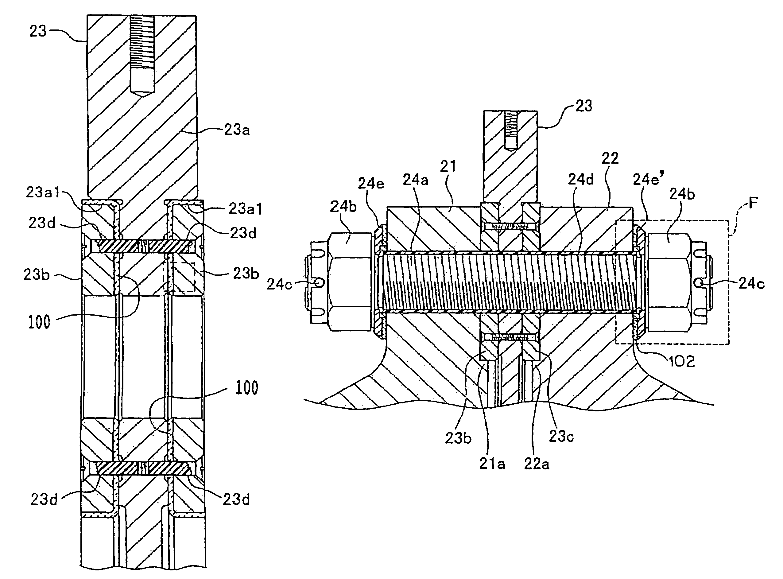
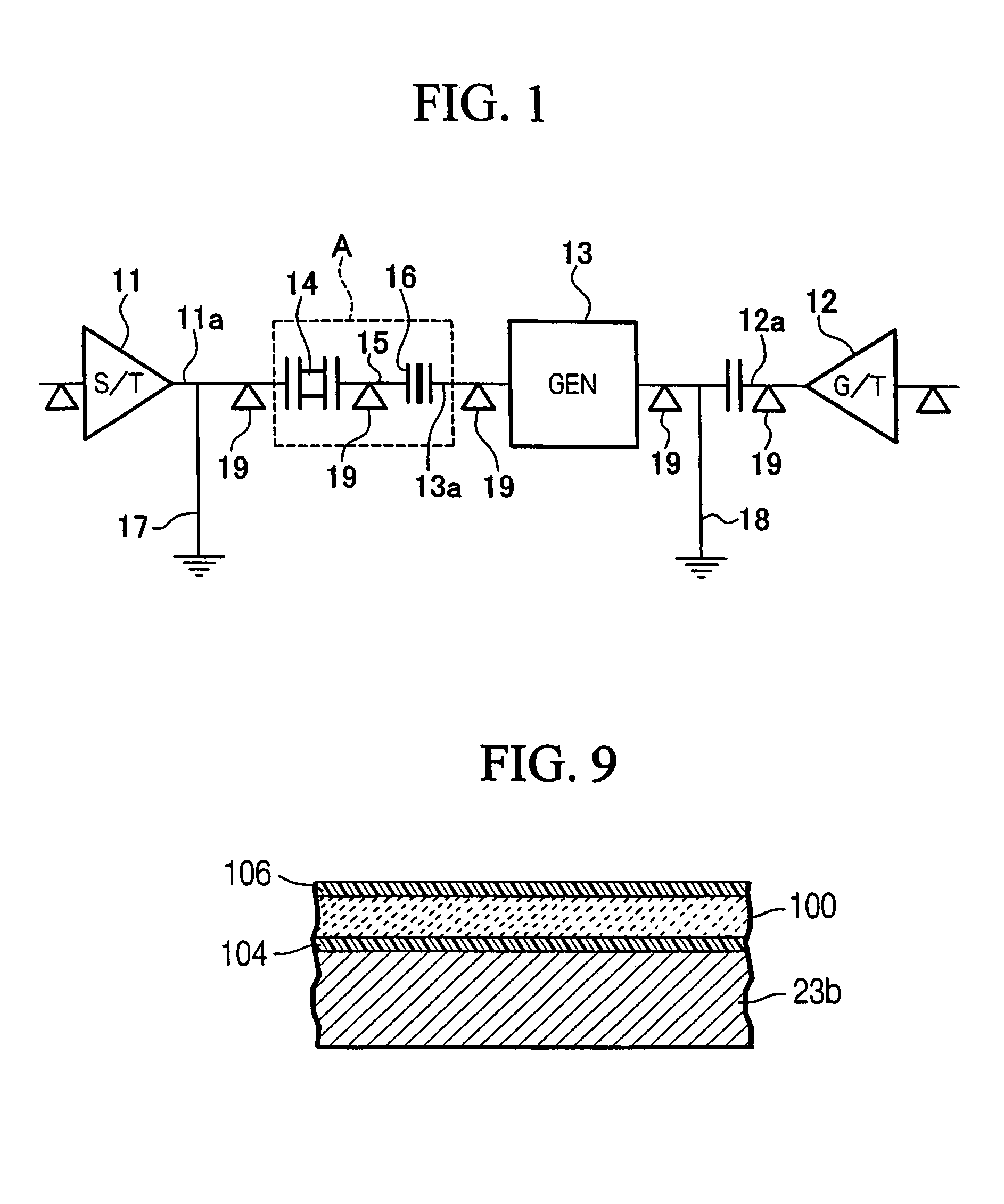
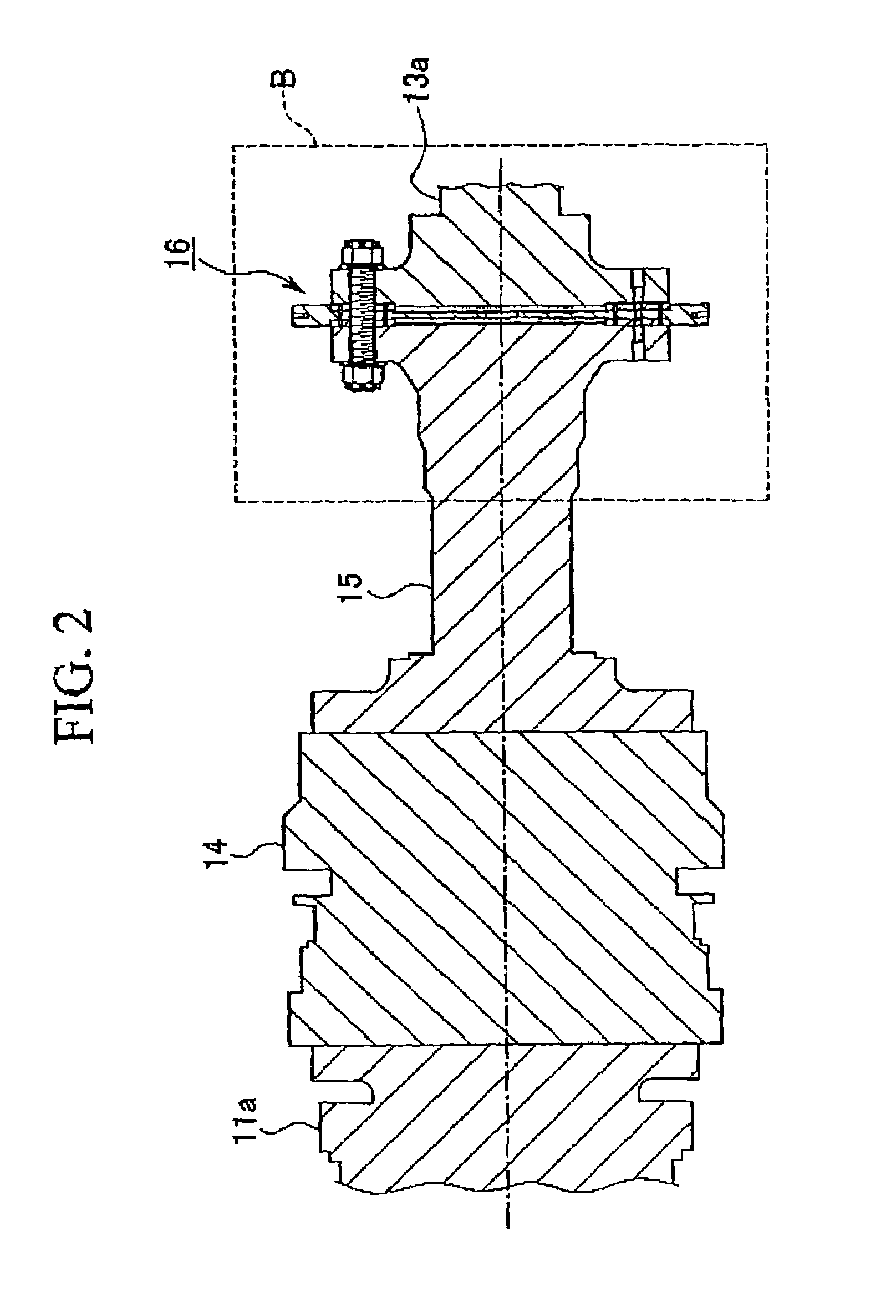
[0033]FIG. 1 is an explanatory figure showing the rough design of a power generating equipment provided with the first embodiment of the rotor coupling having insulated structure of the present invention. FIG. 2 is a vertical cross-sectional view of part A in FIG. 1 showing an essential element of the power generating equipment. FIG. 3 is an enlarged cross-sectional view of part B in FIG. 2 showing the rotor coupling having insulated structure provided to the essential element in the power generating equipment. FIG. 4 is a view of the rotor coupling having insulated structure as seen along arrow C-C in FIG. 3. FIG. 5 is an enlarged cross-sectional view of part D in FIG. 3 showing the rotor coupling having insulated structure. FIG. 6 is an enlarged cross-sect...


PUM

PropertyMeasurementUnit
areaaaaaaaaaaa
corrosionaaaaaaaaaa
shaft voltageaaaaaaaaaa

Abstract

A rotor coupling having insulated structure which can assuredly prevent galvanic corrosion of beating members, rotors and the like which is caused by shaft voltage, is provided in a shaft system that requires insulation. A generator is disposed in between a steam turbine and a gas turbine or a rotating machinery such as another steam turbine. The rotor coupling having insulated structure is employed in power generating equipment in which a generator is disposed in between a steam turbine and a gas turbine or a rotating machinery such as another steam turbine, a generator rotor and a rotating machinery rotor are connected, a first grounding electrode is provided to the steam turbine rotor, and a second grounding electrode is provided to the generator rotor, wherein both the rotors between the generator and the steam turbine are connected in an electrically insulated state.

Description

BACKGROUND OF THE INVENTION[0001]1. Field of the Invention[0002]The present invention relates to a rotor coupling having insulated structure that is preferably employed in power generating equipment in which a generator is disposed in between a steam turbine and a gas turbine or a rotating machinery such as another steam turbine. More specifically, the present invention relates to a rotor coupling having insulated structure that is designed to stop galvanic corrosion of the rotor, bearing members and the like which occurs due to the generation of shaft voltage.[0003]2. Description of the Related Art[0004]An example of conventional power generating equipment will be explained with reference to FIG. 8. In this figure, 1 is a steam turbine, 2 is a generator, and 3 is a gas turbine or a rotating machinery such as another steam turbine (the following explanation employs a gas turbine as an example of this rotating machinery, however the same explanation applies to the case where another ...

Claims


Application Information

Patent Timeline
Patent Type & Authority Patents(United States)
IPC IPC(8): F16D1/02B63H23/34F01D5/06C23C4/00C23C4/08C23C4/10C23C28/00F01D5/02F01D13/00F01D15/10F01D25/00F01K23/14F01K23/16F02C7/36F16D1/033
CPCC23C4/00F01D15/10F01D25/007F01K23/16F02C7/36F16D1/033F01D5/026Y10T403/64F05D2220/74F05D2220/76F05D2220/72F05D2230/90Y10S464/90Y10T403/17Y10T464/30Y10T403/645F16B2200/50F16B2200/506
Inventor TODA, HIDEYUKIISHISAKA, HARUOMORII, YOSHIYUKI
Owner MITSUBISHI HITACHIPOWER SYST LTD
Why Eureka
Try Eureka