Method and apparatus for controlling pitch and flap angles of a wind turbine

a wind turbine and flap angle technology, applied in the field of wind turbines, can solve the problems of large and strong structures, tower strikes or other potentially damaging events, variability in the operation and economics of wind turbines, etc., and achieve the effect of large coupling ratio changes

Inactive Publication Date: 2009-05-12
THE WIND TURBINE
View PDF5 Cites 28 Cited by
  • Summary
  • Abstract
  • Description
  • Claims
  • Application Information

AI Technical Summary

Benefits of technology

[0011]A link with a movable proximal end advantageously is part of the mechanical system. The system can provide relativel

Problems solved by technology

One factor affecting the operation and economics of wind turbines is variability.
Thus, many previous devices required large and strong structures to accommodate, e.g., torque surges, even though, for the majority of the time, such large and strong structures are not needed (i.e. during non-gust conditions).
Variability can also contribute to undesirable movement of blades, potentially in a direction towards the tower or other structures, which, if not pr

Method used


Image

  • Method and apparatus for controlling pitch and flap angles of a wind turbine
  • Method and apparatus for controlling pitch and flap angles of a wind turbine
  • Method and apparatus for controlling pitch and flap angles of a wind turbine

Examples


Embodiment Construction

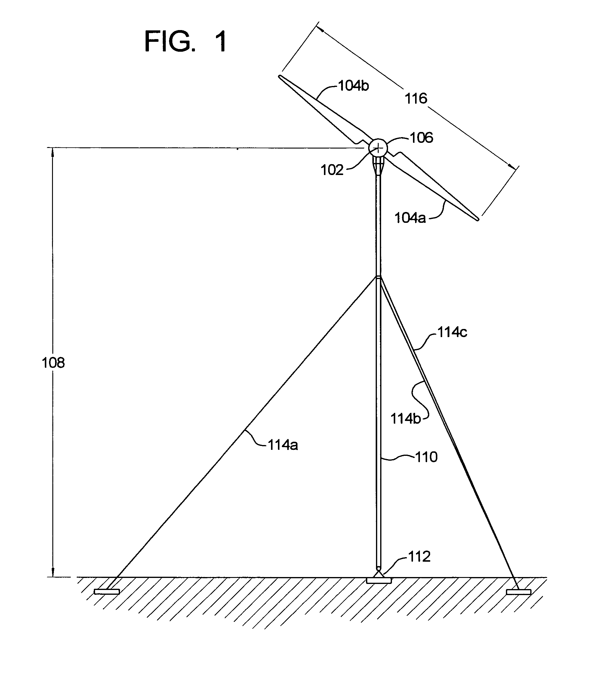
[0028]The present invention can be applied to many configurations of wind turbines, including a variety of sizes and power ratings. FIG. 1 shows one example of a wind turbine that can be used in connection with the present invention. As depicted in FIG. 1, power is generated by rotation of airfoil-shaped blades 104a, 104b about a rotation axis 102, e.g., by transmission of the rotational motion to an electric generator. A number of blade materials can be used, including glass fiber composites. In the depicted embodiment, the generator 106 and blades 104a, 104b are positioned a distance 108 above the surface of the ground by a tower 110 mounted on a base 112 and positioned, e.g., using guy wires 114a, 114b, 114c. In one embodiment, the rotating blades 104a, 104b define a circle having a diameter 116 of about 54 meters. In one embodiment, the height 108 of the tower is about 100 meters.

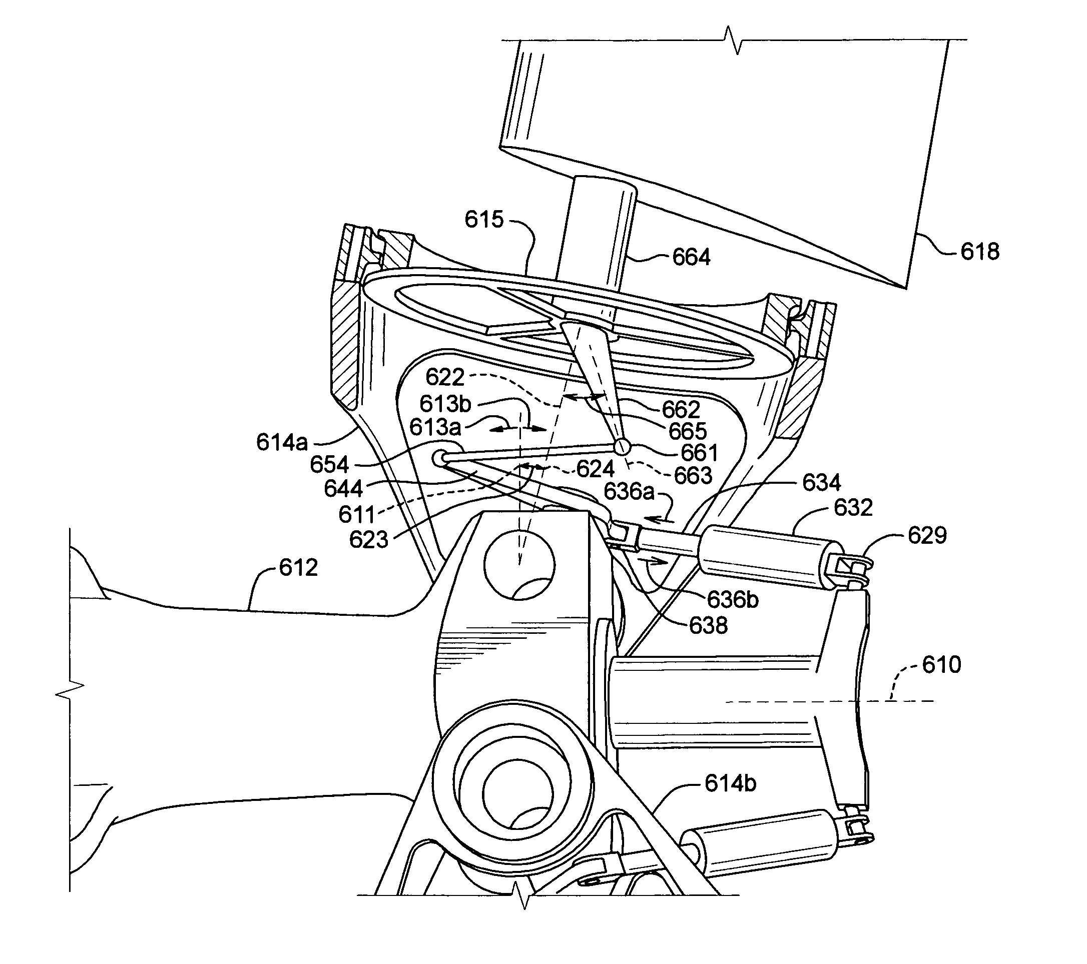
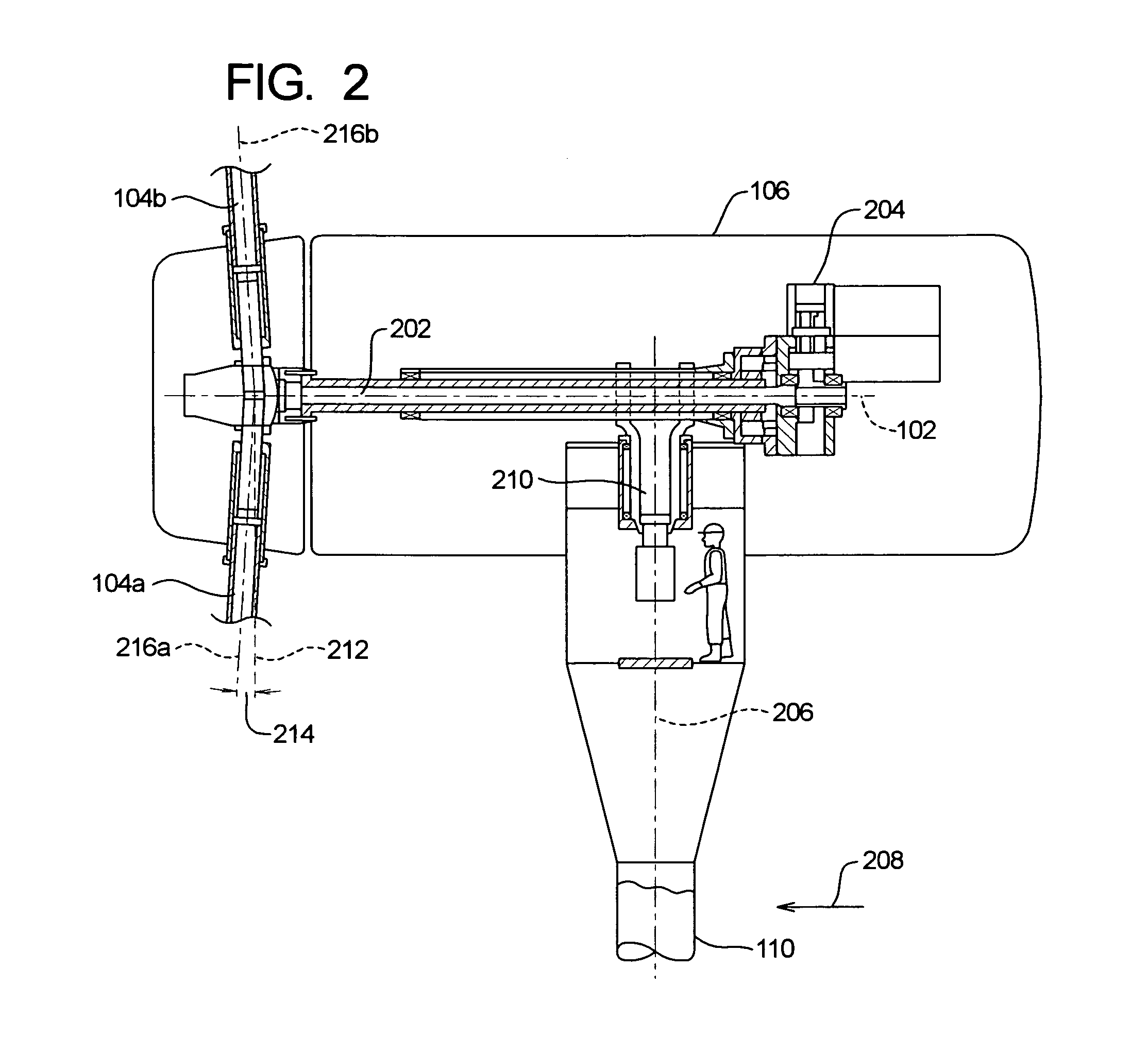
[0029]As depicted in FIG. 2, rotation of the blades 104a, 104b about the rotational axis 102 is tran...


PUM


Abstract

A wind turbine with improved response to wind conditions is provided. Blade flap angle motion is accompanied by a change in pitch angle by an amount defining a pitch/flap coupling ratio. The coupling ratio is non-constant as a function of a flap angle and is preferably a substantially continuous, non-linear function of flap angle. The non-constant coupling ratio can be provided by mechanical systems such as a series of linkages or by configuring electronic or other control systems and/or angle sensors. A link with a movable proximal end advantageously is part of the mechanical system. The system can provide relatively large coupling ratios and relatively large rates of coupling ratio changes especially for near-feather pitches and low flap angles.

Description

FIELD OF THE INVENTION[0001]This invention was made with Government support under the National Renewable Energy Laboratory, under Contract Number ZAM-7-13220-29 awarded by the Department of Energy. The Government has certain rights in this invention. The present invention is directed to a wind turbine and particularly to a device and method for controlling pitch and flap angles of the wind turbine.BACKGROUND INFORMATION[0002]Many attempts have been made to derive useful energy from the wind. In general, design has progressed to the point that, on a per-energy-unit cost basis, wind turbine energy costs approach those of conventional power sources. Because of the size of worldwide power needs, even small incremental changes in wind turbine efficiency can provide substantial benefits.[0003]One factor affecting the operation and economics of wind turbines is variability. The variable nature of wind has, in the past, required devices having sufficient structural strength to withstand the...

Claims


Application Information

Patent Timeline
IPC IPC(8): F03D7/02
CPCF03D1/0658F03D7/0224F05B2260/79Y02E10/721Y02E10/723F05B2240/2022Y02E10/72
Inventor DEERING, KENNETH J.WOHLWEND, KEITH P.
Owner THE WIND TURBINE
Why Eureka
Try Eureka