Optical coupler, a method of its fabrication and use

a technology of optical couplers and optical couplings, applied in the field of optical couplers, can solve the problems of reducing the diameter of the mode field of the signal fiber, the disadvantages of the coupler, and the difficulty of handling, and achieve the effect of low-loss optical coupling

Active Publication Date: 2009-05-12
CRYSTAL FIBRE AS
View PDF43 Cites 272 Cited by
  • Summary
  • Abstract
  • Description
  • Claims
  • Application Information

AI Technical Summary

Benefits of technology

[0010]An object of the present invention is to provide an optical coupler, which is relatively easy to manufacture. It is another object of the invention to provide an optical coupler that is relatively easy to handle. It is a further object to provide an optical coupler that can give a relatively high-power output. It is a further object to provide an optical coupler that can yield a single mode signal feed through with improved control of the mode field diameter.
[0091]In an embodiment, the method provides that the end faces of the input and output sections are adapted to provide a relatively low-loss optical coupling between the input and output sections.

Problems solved by technology

The optical coupler of U.S. Pat. No. 5,864,644 is difficult to handle without introducing impurities to the surfaces of the component which may cause problems in-high power applications.
A disadvantage of this coupler is that the mode field diameter of a signal fiber is smaller at the relatively smaller cross sectional end (the down-tapered end) of the tapered fiber than at the relatively larger cross-sectional end (the un-tapered end).
The coupler has the same disadvantages as mentioned above regarding handling and impurities.
The optical coupler of WO-2005 / 091029 is relatively complex to manufacture, because special care must be taken to avoid the inclusion of impurities and / or air bubbles between the input fibers and the surrounding tube during fusing and tapering.
A problem of the prior art lies in the manufacturing process, specifically in the introduction of impurities during manufacture of an optical coupler, which may degrade performance, especially in high-power applications.
When splicing at such high temperatures, the holes of a possible air-cladding will typically suffer in the heating region (i.e. decrease in cross-sectional area or fully collapse), unless pressurized.
Otherwise, impurities from the coating may decrease the amount of power carried by the coupler.

Method used


Image

  • Optical coupler, a method of its fabrication and use
  • Optical coupler, a method of its fabrication and use
  • Optical coupler, a method of its fabrication and use

Examples


example 1

An Optical Coupler for Providing Pump Light

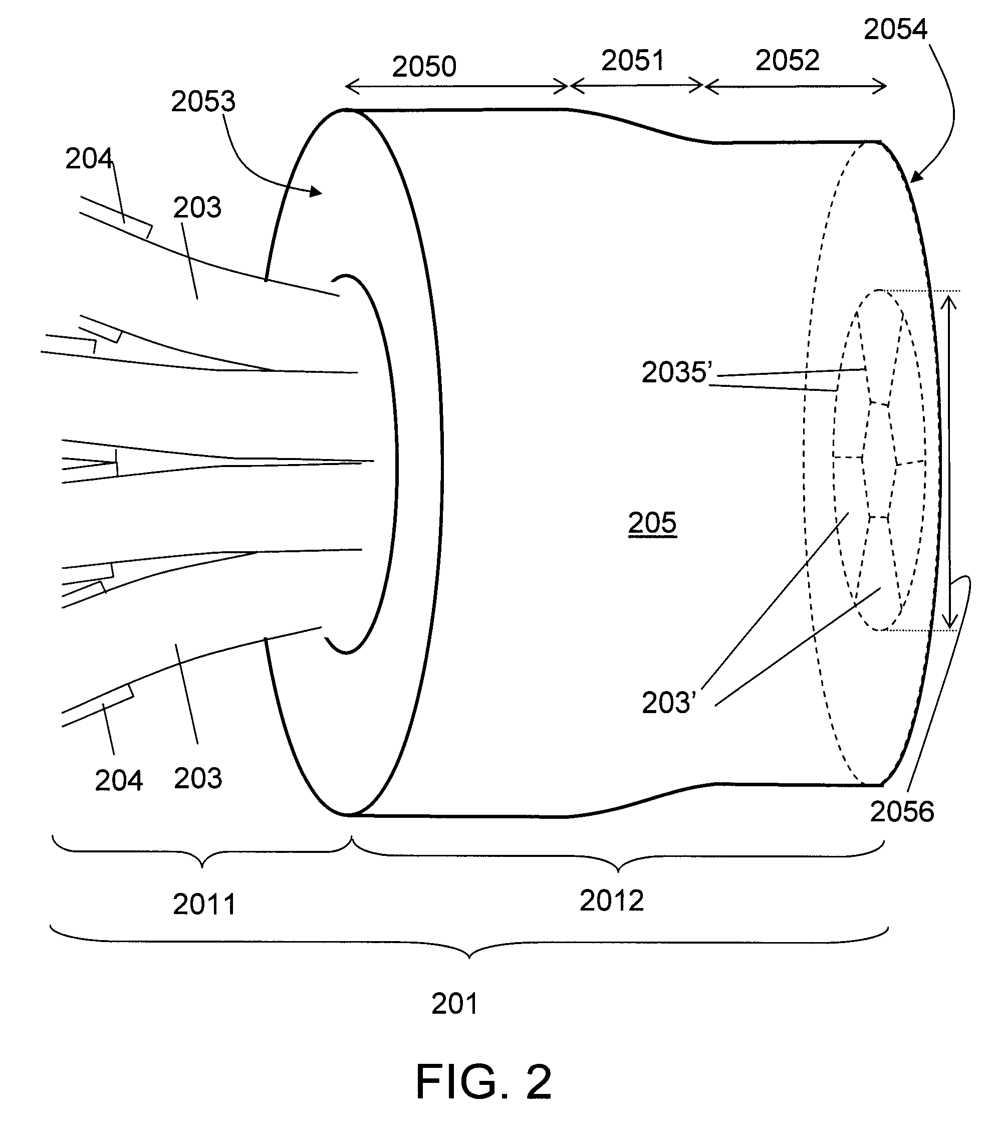
[0159]FIG. 7 shows an embodiment of an optical coupler according to the invention, FIG. 7a schematically illustrating the interface between the input and output sections and FIGS. 7b-7d showing photomicrographs of different cross sections of an implemented device along the length of the coupler.

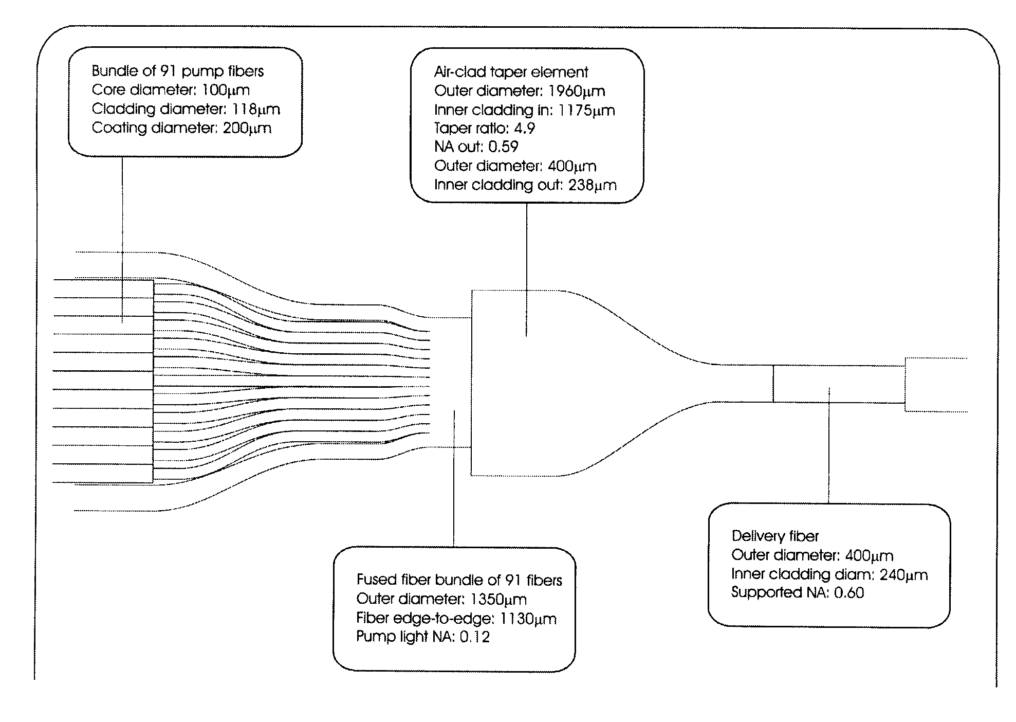
[0160]This section describes the realization of a pump combiner with 7 pump fibers. The combiner is realized using a Vytran GPX-3100 for tapering and fusing, while splicing is performed on a Vytran LDS-1250. On both machines a F100-12525-N10 tungsten filament is used. Cleaving is performed on a Vytran LDC-200. All Vytran apparatuses are from Vytran Corp. (Morganville, N.J., USA).

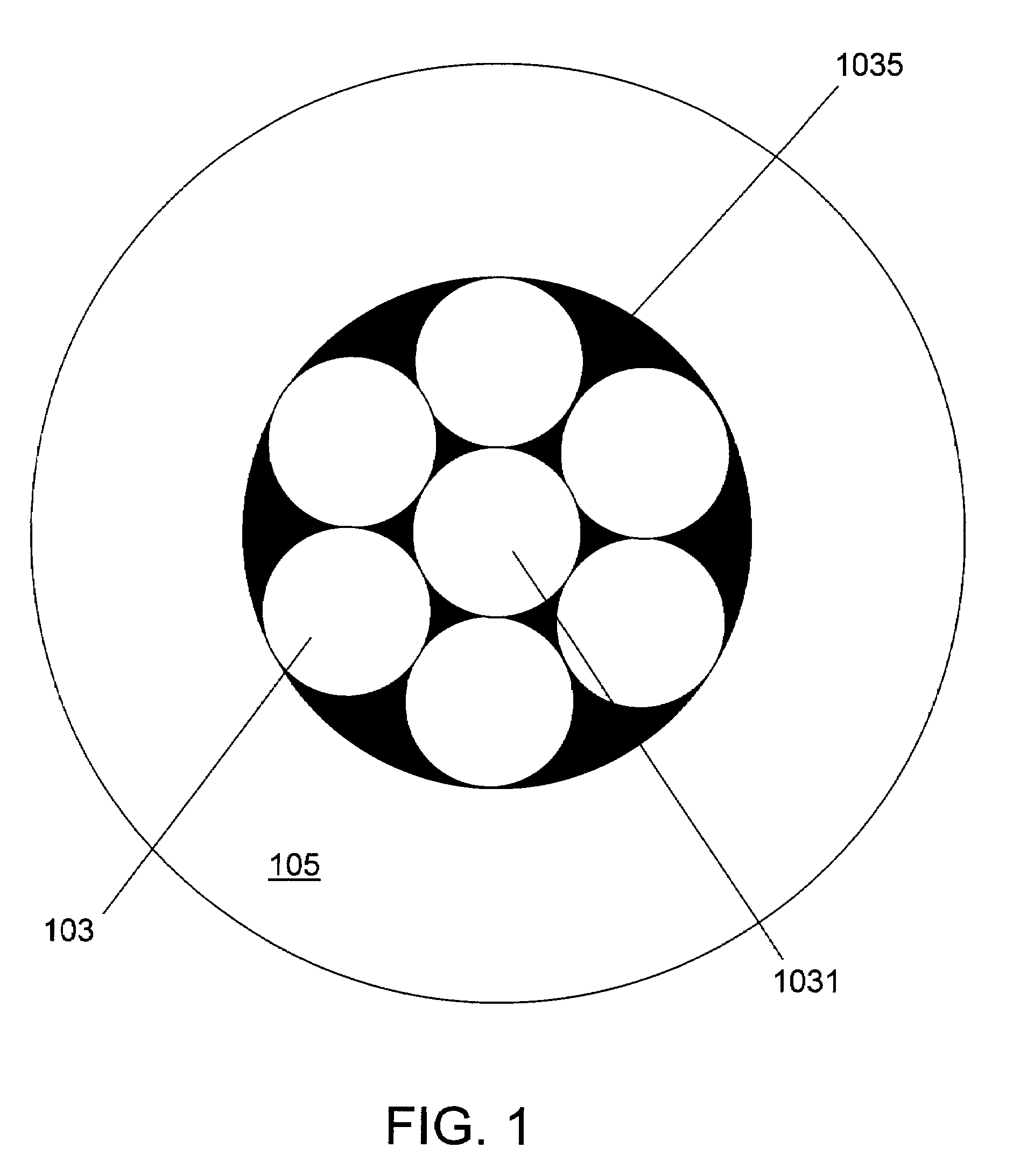
[0161]Seven pump fibers of 0.5 m length were prepared with 6 cm uncoated ends. Pump fibers with 105 μm core, 118 μm outer diameter and 200 μm coating diameter are used. The pump fibers support up to 0.22 NA. Such fibers can e.g. be obtained from LG Optics (Light Guide Optics ...

example 2

An Optical Coupler with Signal Feed Through

[0177]The present example deals with an optical coupler suitable for use in a fiber amplifier, wherein the input section comprises a centrally located signal fiber surrounded by a number of pump fibers and wherein the tapered output section of the optical coupler comprises a centrally located region adapted for guiding the signal light in a single mode and surrounded by a region for guiding the pump light.

[0178]In prior art tapered fiber bundle couplers, the same fibers constitute the cross section at every point from input to tapered output. In the approach described here a single-mode fiber and a number of pump fibers are fused together in a bundle and subsequently cleaved without tapering to create an output face of an input section of the coupler. The fused bundle is then spliced to the output section in the form of a double clad fiber, which is cleaved (to form an input end face) and tapered. The other end of the output section of the ...

example 3

An All-Solid Signal Feed-Through Fiber

[0190]This aspect relates also to the published PCT-application WO 2005 / 091029 and can be used in connection with but is NOT restricted to use in the above described ‘two-part’ optical coupler (but can be used in couplers based on a tapered bundle of fibers).

[0191]The idea is to substitute air-holes in the micro-structured feed-through fiber with solid glass inclusions having lower refractive index than the base material (e.g. silica). This eliminates the problem of holes in the feed-through fiber collapsing when this is incorporated into the fused bundle, tapered and spliced. Collapsing of holes is a major concern since the fusing of pump and signal fibers into a round bundle require excessive heat.

[0192]In its broadest aspect, the idea thus covers an optical coupler for coupling light from at least two input fibers into one output fiber, the optical coupler comprising a microstructured feed-through fiber with solid glass inclusions having lowe...


PUM

PropertyMeasurementUnit
lengthaaaaaaaaaa
tapering lengthaaaaaaaaaa
diameteraaaaaaaaaa

Abstract

An optical coupler for coupling light from at least two input fibers into one output fiber and a method of fabricating and use of an optical coupler. The coupler comprises a) an input section comprising an output end face at one end of the bundling-length of input fibers; and b) an output section comprising an output fiber comprising a confining region for confining light propagated in the input fibers and a surrounding cladding region and having an input end face; wherein the output end face of said input section is optically coupled to the input end face of the output section and at least the confining region of the output fiber is tapered down from a first cross sectional area at the input end face to a second, smaller cross sectional area over a tapering-length of the output fiber.

Description

TECHNICAL FIELD[0001]The present invention relates in general to coupling of light between input and output waveguides.[0002]The invention relates specifically to an optical coupler for coupling light from at least two input fibers into one output fiber.[0003]The invention furthermore relates to a method of fabricating an optical coupler for coupling light from at least two input fibers into one output fiber.[0004]The invention furthermore relates to the use of an optical coupler, to an optical coupler obtainable by the method and to an article comprising an optical coupler.[0005]The invention may e.g. be useful in applications such as fiber lasers or amplifiers, where efficient coupling of light from a number of pump sources to a single (e.g. double clad) output fiber is needed. The invention is useful in applications where very high powers (e.g. more than 50 W-100 W) are to be combined from a multitude of individual input fibers into one output fiber. It is further useful in appli...

Claims


Application Information

Patent Timeline
Patent Type & Authority Patents(United States)
IPC IPC(8): G02B6/26G02B6/28
CPCG02B6/02376G02B6/2856G02B6/02333G02B6/02366G02B6/0238H01S3/094053
Inventor SKOVGAARD, PETER M. W.NIELSEN, MARTIN DYBENDAL
Owner CRYSTAL FIBRE AS
Why Eureka
Try Eureka