Multi-layer ring seal

a multi-layer, sealing technology, applied in the direction of machines/engines, liquid fuel engines, mechanical equipment, etc., can solve the problems of reducing the interlaminar tensile strength of materials, complicated active cooling systems, and affecting the performance of materials,

Inactive Publication Date: 2009-05-19
SIEMENS ENERGY INC
View PDF21 Cites 38 Cited by
  • Summary
  • Abstract
  • Description
  • Claims
  • Application Information

AI Technical Summary

Problems solved by technology

Such active cooling systems are usually complicated and costly.
However, CMC materials have their own drawbacks.
In addition, anisotropic shrinkage of the matrix and the fibers can result in de-lamination defects, particularly in small radius corners and tightly-curved sections, which can further reduce the interlaminar tensile strength of the material.

Method used


Image

  • Multi-layer ring seal
  • Multi-layer ring seal
  • Multi-layer ring seal

Examples


Embodiment Construction

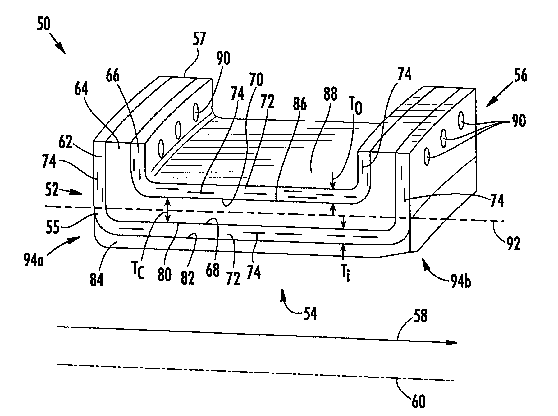
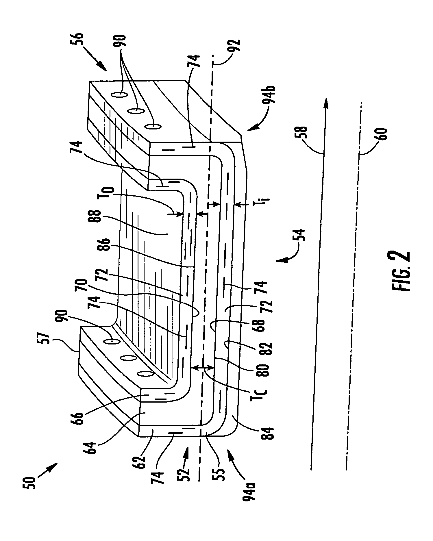
[0022]Embodiments of the invention are directed to a construction that can allow multiple material systems to be used in a ring seal or a ring seal segment for a turbine engine. Aspects of the invention will be explained in connection with one possible ring seal segment, but the detailed description is intended only as exemplary. An embodiment of the invention is shown in FIGS. 2-3, but the present invention is not limited to the illustrated structure or application.

[0023]FIG. 2 shows a ring seal body according to aspects of the invention. The ring seal body can be, for example, a ring seal segment 50. The ring seal segment 50 has a forward span 52, an extension 54 and an aft span 56. The extension 54 transitions into the forward span 52 in a first region 94a; the extension 54 transitions into the aft span 56 in a second region 94b that is opposite the first region 94a. The terms “forward” and “aft” are intended to mean relative to the direction of the gas flow 58 through the turbin...


PUM

PropertyMeasurementUnit
anglesaaaaaaaaaa
angleaaaaaaaaaa
thicknessaaaaaaaaaa

Abstract

Aspects of the invention are directed to a multi-layer ring seal segment that can incorporate a plurality of material systems. The ring seal segment can include an inner layer, a central layer and an outer layer. The inner layer can be attached to one side of the central layer, and the outer layer can be attached to an opposite side of the central layer. The inner and outer layers can be made of a ceramic matrix composite, such as a hybrid oxide ceramic matrix composite or an oxide-oxide ceramic matrix composite. The central layer can be made of a material that has high shear strength relative to the inner and outer layers. The ring seal segment according to aspects of the invention can take advantage of the benefits of the different materials so as to better withstand the operational loads of the turbine.

Description

FIELD OF THE INVENTION[0001]Aspects of the invention relate in general to turbine engines and, more particularly, to ring seals in the turbine section of a turbine engine.BACKGROUND OF THE INVENTION[0002]FIG. 1 shows an example of one known turbine engine 10 having a compressor section 12, a combustor section 14 and a turbine section 16. In the turbine section 16 of a turbine engine, there are alternating rows of stationary airfoils 18 (commonly referred to as vanes) and rotating airfoils 20 (commonly referred to as blades). Each row of blades 20 is formed by a plurality of airfoils 20 attached to a disc 22 provided on a rotor 24. The blades 20 can extend radially outward from the discs 22 and terminate in a region known as the blade tip 26. Each row of vanes 18 is formed by attaching a plurality of vanes 18 to a vane carrier 28. The vanes 18 can extend radially inward from the inner peripheral surface 30 of the vane carrier 28. The vane carrier 28 is attached to an outer casing 32,...

Claims


Application Information

Patent Timeline
Patent Type & Authority Patents(United States)
IPC IPC(8): F01D11/08
CPCF01D11/08F16J15/104F05D2250/70F05D2250/712F05D2300/21F05D2300/603
Inventor MAZZOLA, STEFANKELLER, DOUGLAS A.SCHIAVO, ANTHONY L.RADONOVICH, DAVID C.
Owner SIEMENS ENERGY INC
Why Eureka
Try Eureka