Process for impregnating a fibrous, filamentary and/or porous network with powder using electrodes subjected to an AC electric field

a technology of ac electric field and impregnating capacity, applied in the field of new materials, can solve the problems of reducing the mechanical properties of composite materials, requiring a substantial energy consumption, and limiting the amount of powder used, so as to improve the impregnating capacity of the set up, prevent electrical microdischarge, and improve the effect of impregnating capacity

Inactive Publication Date: 2009-05-19
MATERIALS TECHNICS HLDG SA
View PDF9 Cites 6 Cited by
  • Summary
  • Abstract
  • Description
  • Claims
  • Application Information

AI Technical Summary

Benefits of technology

[0017]The electrodes consist of highly conducting elements in order to guarantee an equivalent voltage at every point on their surface and to minimize heating losses. Metals such as, for example, copper, aluminum, silver or gold are advantageously indicated for this.
[0019]The insulators used in the process must have a high dielectric strength and exhibit good aging behavior. Materials such as quartz, glass or ceramic exhibit characteristics that are useful for forming this dielectric. These materials allow little space charge to accumulate when they are subjected to an electric field. Quartz is of particular value as a dielectric insulator as it has a high dielectric strength and good aging behavior.
[0022]The use of resins highly filled with metal particles (silver lacquer for example) allows direct production of a coating serving as electrode on the surface of the dielectric insulator. Likewise, the use of metal films covered with adhesive allows the electrode to be applied directly to the dielectric insulator without having an air layer between the electrode and the dielectric. Another particularly advantageous solution consists in directly metallizing the dielectric insulator using one of the various metallization techniques well known in the art (PVD or CVD vacuum metallization, chemical metallization, etc.). Here again, the absence of an air layer between the electrode and the dielectric insulator is favorable in order to prevent electrical microdischarges between the two elements.
[0023]According to the invention, the upper electrode comprises at least one electrode tube. Any deformation at the center of this electrode is thus greatly reduced, thereby making it possible to carry out treatments over large widths of at least 0.80 m, particularly 1.20-7.00 m. The conventional layout of electrodes is perpendicular to the direction of movement of the product to be treated. Other layouts may be used with electrodes orientated from 0 to 90° compared with the conventional layout. The interest of a layout that is not perpendicular to the direction of movement is the possibility of using electrodes that are shorter than the width of the substrate to be treated, notably when the latter has a large width.
[0024]The electrode tube or tubes may have a circular or rectangular cross-section, or one of another shape, allowing a uniform field to be applied. That cross-section may also have a more complex shape that allows punctually concentrating the field lines, thereby enhancing the impregnating capacity of the set up. The electrode tubes generally consist of a dielectric and of a metal part.

Problems solved by technology

Consequently, the higher the void content the lower the mechanical properties of the composite.
The difficulty in the case of hot-melt adhesive powders is that it requires the use of a process allowing the powders to be distributed at the points of intersection of the fibers, in order to optimize bonding, while limiting the amount of powder used.
The case of active principles in liquid form has the drawback of requiring a substantial consumption of energy in order to be able to dry them, while evaporating the solvent from the solution.
Powders do not have this type of problem, but they are sometimes difficult to distribute uniformly and definitively within the base textile.
That process has many advantages, but it is ill-suited to the impregnation treatment of large articles, for example those from 0.80 to 7.00 m in width, in particular when the continuous treatment is carried out with a material running between the electrodes.
This is because any geometrical distortion of the electrodes results in variations in the distance between them, which degrades the uniformity of the electric field and therefore the quality of powder impregnation.
To avoid this geometrical distortion, the lower metal plate electrode may be placed on a stand; however, the upper metal plate electrode and the dielectric that covers it therefore have to be stiffened, for example by transverse bars, which may impair the operation of the electrodes.

Method used


Image

  • Process for impregnating a fibrous, filamentary and/or porous network with powder using electrodes subjected to an AC electric field
  • Process for impregnating a fibrous, filamentary and/or porous network with powder using electrodes subjected to an AC electric field
  • Process for impregnating a fibrous, filamentary and/or porous network with powder using electrodes subjected to an AC electric field

Examples


example 1

[0054]This example was produced with a nonwoven made of natural hemp fibers, weighing 1000 g / m2 and being 9 mm in thickness, and with thermosetting powder of the Bakelite brand, reference 6171TP, having a particle size of less than 100 μm. The upper face of the nonwoven was precoated with 500 g / m2 of powder.

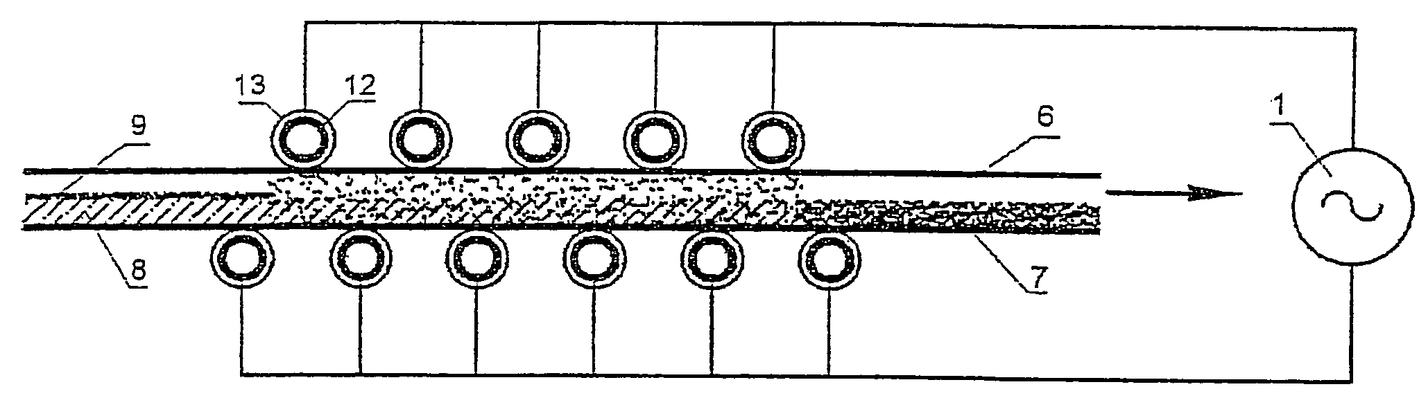
[0055]The whole assembly was then introduced into the impregnation process between two belts at a rate of 2 meters per minute. The electrodes used were tubular electrodes 30 mm in outside diameter, which were placed facing one another. The space separating the upper and lower electrodes was 10 mm between dielectrics. The space between two tubular electrodes of the same potential was 15 mm, i.e. 23 electrodes on each side for a treatment length of 1 meter. A field of 3 kV / mm was applied between the belts in the space where the material to be impregnated was. A residence time of 30 seconds in the machine allowed the nonwoven to be uniformly impregnated with powder.

[0056]After impre...

example 2

[0057]This example was produced with a viscose / polyester spun lace nonwoven weighing 100 g / m2. The surface of the nonwoven was precoated with superabsorbent powder of reference JB 882 from SNF, the powder having a particle size of less than 100 μm.

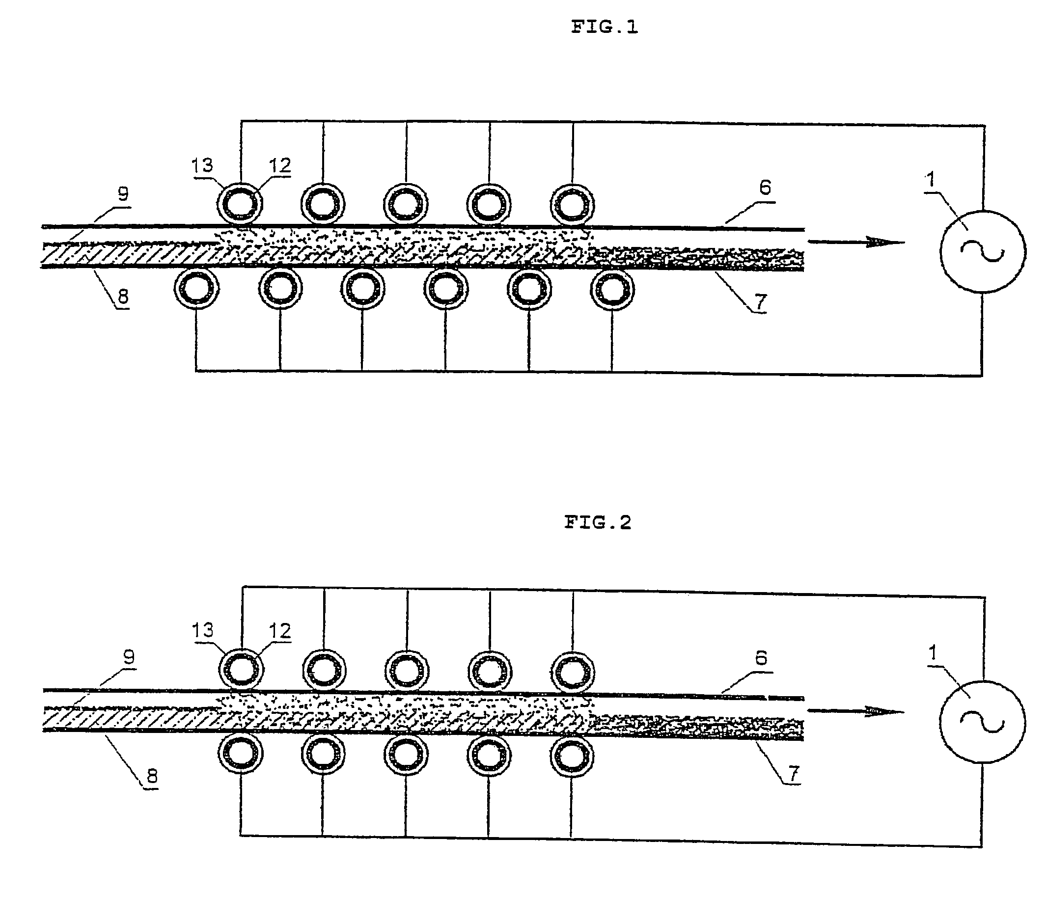
[0058]The speed of the belts allowing the material to be introduced into the impregnation machine was 4 m / min. The impregnation time was therefore 15 seconds in order to impregnate the superabsorbent into the nonwoven. The electrodes used were tubular electrodes 30 mm in outside diameter in the case of the upper electrode and a flat electrode coated with a 4 mm thick dielectric in the case of the lower electrode. The space separating the upper and lower electrodes between dielectrics was 5 mm. The space between two upper tubular electrodes was 15 mm, i.e. 23 electrodes. The dimensions of the lower flat electrode were 1 m×1 m. The electric field applied to the product was 4 kV / mm.

[0059]It was found that the impregnating powder positioned it...

example 3

[0061]The objective of this example was to thermally set a polyester nonwoven after carding so as to provide it with sufficient mechanical strength for it to be handled and transported. The nonwoven was a 400 g / m2 polyester, which was carded and formed into a web with a thickness of 50 mm. The thermal bonding powder used was a copolyamide powder having a particle size of 80-200 μm obtained from Abifor.

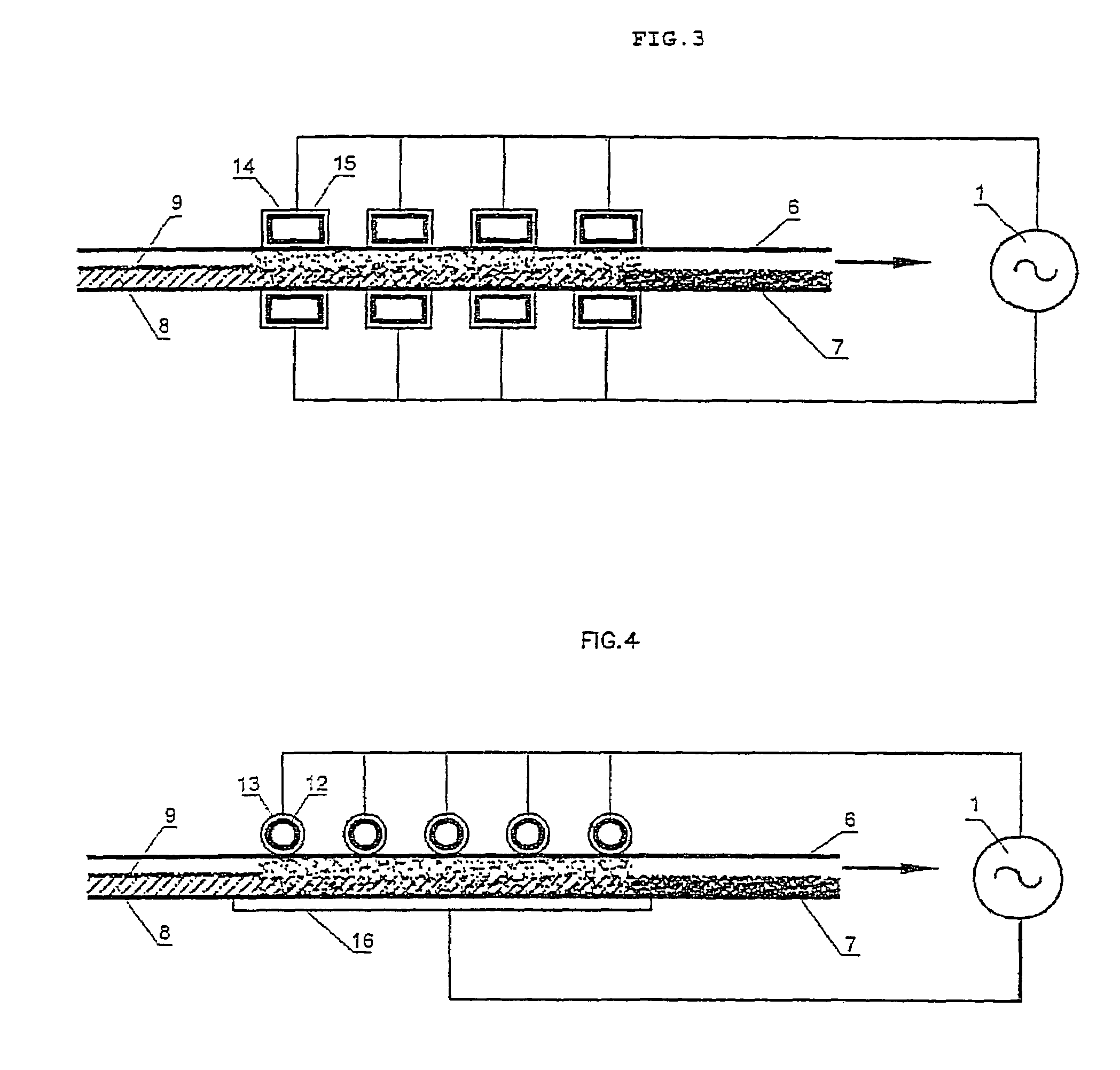
[0062]After the phase of powder-dusting the surface of the nonwoven, the material was compressed to 30 mm between the belts so as to be introduced into the impregnation machine. The electrodes used were tubular electrodes 30 mm in outside diameter, which were arranged in a staggered fashion. The space between two tubular electrodes of the same potential was 15 mm, i.e. 23 electrodes on each side for a treatment length of 1 meter. A speed of 2 m / min was used, i.e. an impregnation time of 30 seconds; this allows all of the thermal bonding powder to be dispersed within the volume of the n...


PUM

PropertyMeasurementUnit
electric fieldaaaaaaaaaa
AC voltageaaaaaaaaaa
widthaaaaaaaaaa

Abstract

The invention relates to a novel electric powder impregnation process for impregnating powder into a fibrous, filamentary and / or porous network, especially in order to produce a composite, comprising a continuous, rigid or flexible, matrix with which said network is in intimate contact, in which process the powder on the one hand and said network on the other are placed between a lower electrode and an upper electrode, these electrodes are electrically insulated from each other by a dielectric and connected to the respective poles of an AC generator so as to simultaneously subject the powder and said network to an electric field, characterized in that the upper electrode comprises at least one electrode tube and the AC electric field applied is from 0.10 to 20 kV / mm.

Description

CROSS REFERENCE TO RELATED APPLICATIONS[0001]This application is a continuation of PCT / IB04 / 03427 filed Oct. 18, 2004, claiming priority of European Application No. 03292607.3 filed Oct. 21, 2003, and are both included in their entirety by reference made hereto.BACKGROUND OF THE INVENTION[0002]1. Field of the Invention[0003]The present invention relates to a novel process for impregnating a fibrous, filamentary and / or porous network with powder, especially in order to produce a composite comprising a continuous, rigid or flexible, matrix with which said network is in intimate contact.[0004]2. Description of the Related Art[0005]Composites reinforced by fibers embedded in thermoplastic or thermosetting matrices are an extremely interesting class of materials, allowing in particular the production of materials exhibiting excellent mechanical properties for masses substantially less than those of metals. Furthermore, these materials are obtained by simple molding, after having coated t...

Claims


Application Information

Patent Timeline
Patent Type & Authority Patents(United States)
IPC IPC(8): B05D1/04B29B15/10B29C70/46B29C70/54C08J5/04D06M23/08H05B6/62
CPCB29C70/465B29C70/546D06M23/08H05B6/62B29B15/12C08J5/04B29B15/10
Inventor MARDUEL, JORIC
Owner MATERIALS TECHNICS HLDG SA
Why Eureka
Try Eureka