Motorized system integrated control and diagnostics using vibration, pressure, temperature, speed, and/or current analysis

Inactive Publication Date: 2009-05-26
ROCKWELL AUTOMATION TECH
View PDF61 Cites 275 Cited by
  • Summary
  • Abstract
  • Description
  • Claims
  • Application Information

AI Technical Summary

Benefits of technology

[0014]In addition to component diagnostic information, the invention provides for detecting, diagnosing, and/or adaptive control according to other detected system operating conditions. For instance, the diagnostics system may be advantageously employed in order to detect and diagnose cavitation, blockage, and/or the like in a motorized pump or in the system in which the motorized pump is employed. In this regard, pressure and flow information related to the pumping system may be measured and cavitation conditions may be identified using a classifier system, such as a neural network. The diagnostics system may thus comprise such a classifier system for detecting pump cavitation according to flow and pressure data. The invention may be employed in cavitation monitoring, as well as in control equipment associated with pumping systems, whereby pump wear and failure associated with cavitation conditions may be reduced or eliminated.
[0015]Such pumping system cavitation conditions may alternatively or in combination be diagnosed u

Problems solved by technology

Although operation of such motorized systems and controllers may achieve system operation in accordance with the setpoint, other factors such as system component wear, component faults, or other adverse conditions, and the like, may affect the operation of the motorized system.
Thus, for example, degradation in a pump impeller in a motorized pumping system may lead to premature catastrophic failure of the system if left unchecked.
In this regard, operation of the pump strictly in accordance with a flow rate setpoint may accelerate the system component wear, degradation, and/or failure, whereas operation at other flow rates may allow the system to last longer.
For instance, the motorized pumping system may be located on board a military vessel at sea, wherein operation according to a flow setpoint may lead to catastrophic p

Method used


Image

  • Motorized system integrated control and diagnostics using vibration, pressure, temperature, speed, and/or current analysis
  • Motorized system integrated control and diagnostics using vibration, pressure, temperature, speed, and/or current analysis
  • Motorized system integrated control and diagnostics using vibration, pressure, temperature, speed, and/or current analysis

Examples


Embodiment Construction

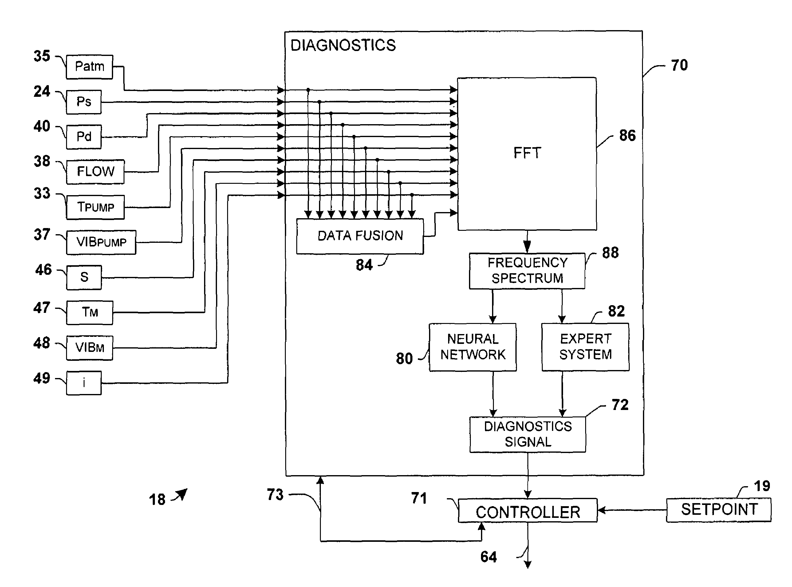
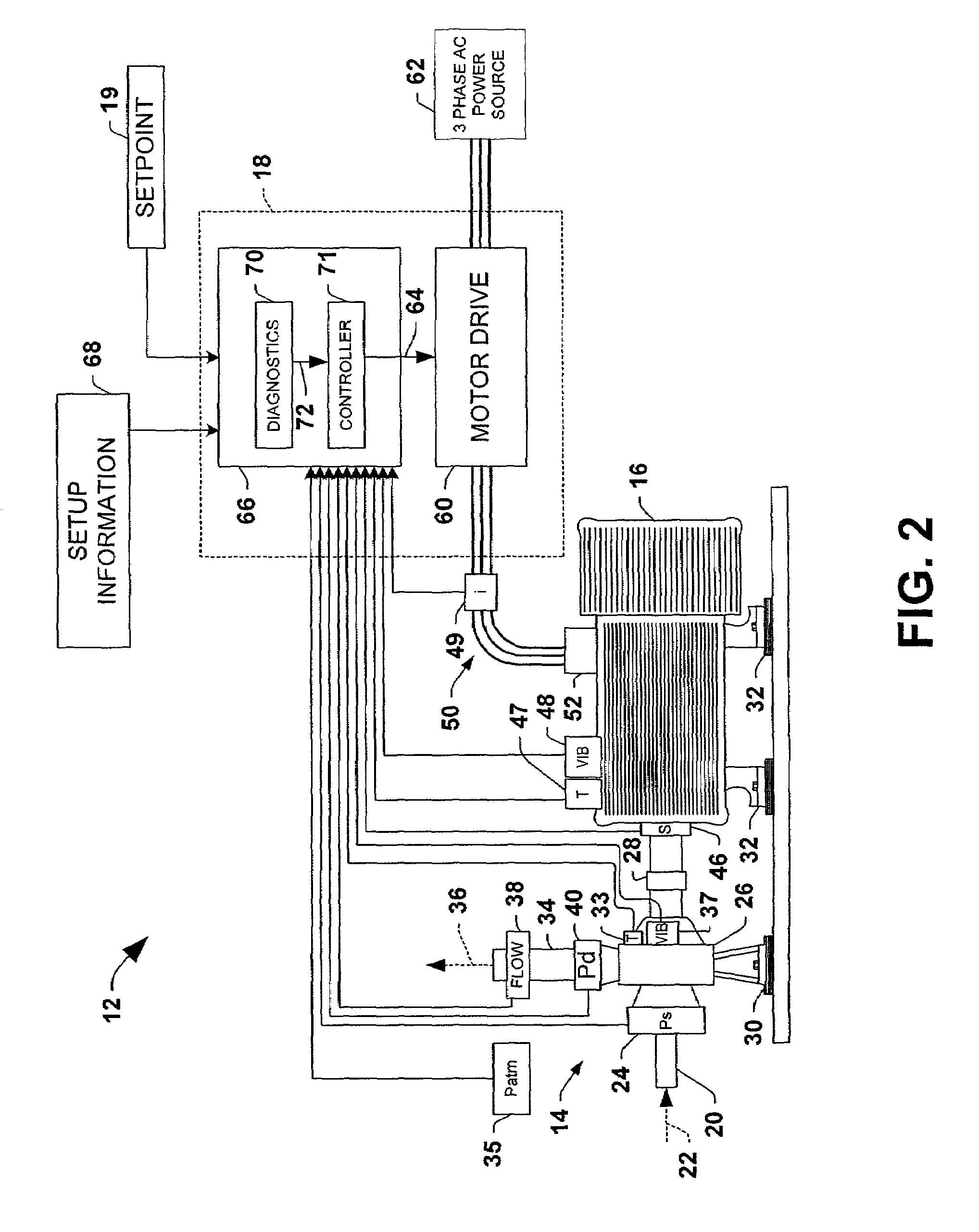
[0070]The various aspects of the present invention will now be described with reference to the drawings, wherein like reference numerals are used to refer to like elements throughout. The invention provides a diagnostics and control system for controlling a motorized system and diagnosing the health thereof, with a controller operatively associated with the motorized system and adapted to operate the motorized system in a controlled fashion, and a diagnostics system operatively associated with the motorized system and adapted to diagnose the health of the motorized system according to a measured attribute associated with the motorized system.

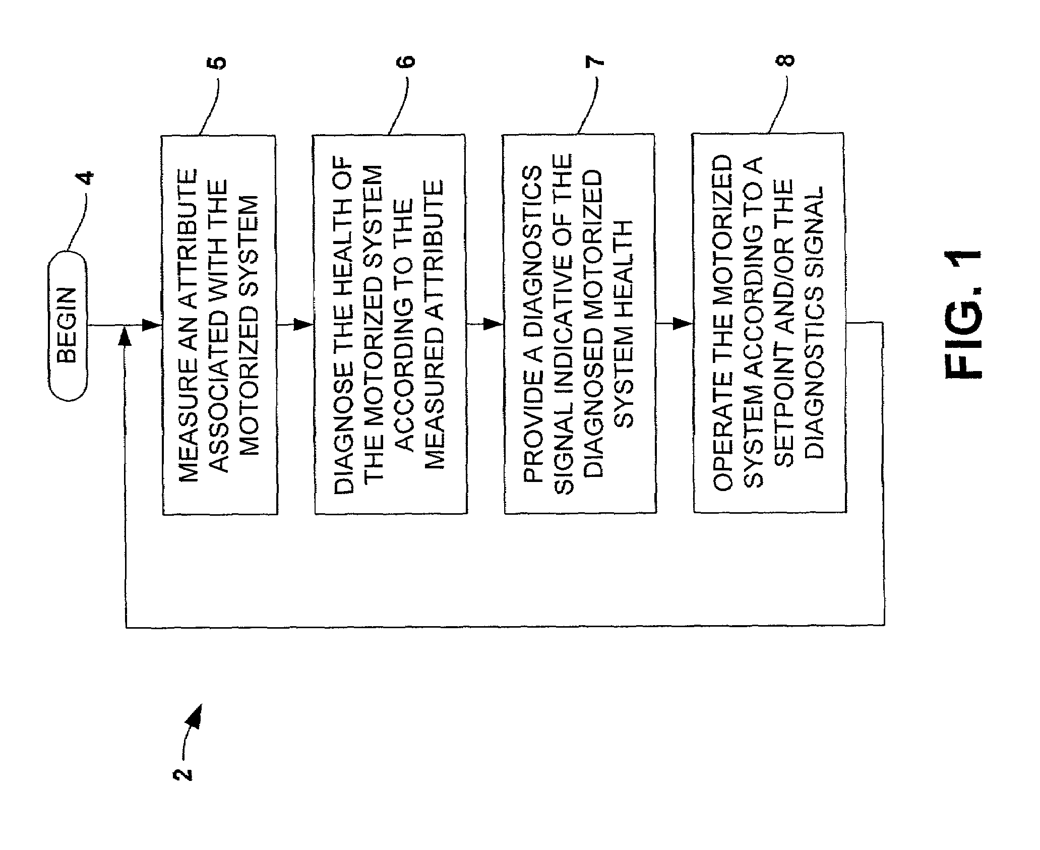
[0071]Referring initially to FIG. 1, an exemplary method 2 is illustrated for controlling a motorized system and diagnosing the health thereof. The method 2 comprises operating a motor in the motorized system in a controlled fashion, and diagnosing the health of the motorized system according to a measured attribute associated with the motorized...


PUM


Abstract

Systems and methods are disclosed for controlling and diagnosing the health of a motorized system. The systems may comprise a diagnostics system and a controller, wherein the diagnostics system employs a neural network, an expert system, and/or a data fusion component in order to assess the health of the motorized system according to one or more attributes associated therewith. The controller may operate the motorized system in accordance with a setpoint and/or a diagnostics signal from the diagnostics system. Also disclosed are methodologies for controlling and diagnosing the health of a motorized system, comprising operating a motor in the motorized system in a controlled fashion, and diagnosing the health of the motorized system according to a measured attribute associated with the motorized system, wherein the motor may be operated according to a setpoint and/or the diagnostics signal.

Description

CROSS REFERENCE TO RELATED APPLICATIONS[0001]This application is a continuation-in-part of application Ser. Nos. 09 / 407,617, filed on Sep. 28, 1999, now U.S. Pat. No. 6,757,665; 09 / 163,933, filed on Sep. 29, 1999, now U.S. Pat. No. 6,289,735; and 09 / 461,787, filed on Dec. 15, 1999, now U.S. Pat. No. 6,326,758, the disclosures of which are hereby incorporated by reference as if fully set forth herein.FIELD OF THE INVENTION[0002]The invention described below generally relates to controlling and diagnosing the health of a machine, and more particularly, to systems and methods for controlling and diagnosing motorized systems according to vibration, pressure, temperature, speed, and / or current analysis.BACKGROUND OF THE INVENTION[0003]Many industrial processes and machines are controlled and / or powered by electric motors. Motorized systems include pumps providing fluid transport for chemical and other processes, fans, conveyor systems, compressors, gear boxes, motion control devices, scr...

Claims


Application Information

Patent Timeline
IPC IPC(8): G05B13/02
CPCF04D15/0077F04D15/0088F04D27/001F04D29/669G01R31/2846G01R31/343G05B23/024G06N3/08G06N3/043
Inventor DISCENZO, FREDUNSWORTH, PETERVETCHA, SARAT BABULOPARO, KENNETH A.DISTER, CARL J.TOMKIN, EDWARD J.
Owner ROCKWELL AUTOMATION TECH
Why Eureka
Try Eureka