
Electrical tissue stimulation apparatus and method

a technology of electric tissue and electrodes, applied in the field of implantable leads, can solve the problems of affecting the effect of the patient's treatment, the electrodes are not very useful in delivering therapeutic current, and the half-section of each electrode is facing away from the tissue of interest, so as to achieve the effect of convenient removal

Inactive Publication Date: 2009-06-09
MEDTRONIC INC
View PDF73 Cites 82 Cited by
  • Summary
  • Abstract
  • Description
  • Claims
  • Application Information

AI Technical Summary

Benefits of technology

[0020]This invention relates to implantable leads for delivering electrical stimulation to tissue in the human body. Specifically, this invention relates to implantable leads that have thin, wire-like, moveable elongate members that may be elastically deformed, but with a distal tip that can curl up in a space inside the body to form a 2- or 3-dimensional electrode for delivery of electrical pulses. Members can be positioned axially or at variable non-axial distances from the lead body. This invention also relates to mechanisms for accomplishing the insertion of multiple electrodes in a manner that is minimally invasive, even through a narrow lumen like a vertebral foramen. An array of such electrodes can also be easily removed without major surgical intervention.
[0028]In another embodiment, a coiled conductor may be found only at the distal end of the extendable member, with most of the length of the member being a simple metal wire, insulated to prevent current loss except at the conducting tip. This coiled conductor may screw on to the end of the wire.
[0029]In order to prevent curling of the electrode before the end of the extendable member is in its final position, the tip of the member may be coated with a material that keeps it rigidly straight. This material would dissolve over time in the environment of the body, allowing curling of the tip into an electrode. The material may also have a sharp point, to make the deployment of the member through adhesions or other tissue easier.

Problems solved by technology

On the other hand, the designs of lead structure that may be incorporated into percutaneous leads are limited because the lead diameter or cross-section must be small enough to permit the lead to pass through the Tuohy needle, generally less than 2.0 mm diameter.
Of course, half of each of these electrodes, facing away from the tissue of interest, is not very useful in delivering therapeutic current.
One disadvantage recognized in known paddle leads is that their installation, repositioning and removal necessitates laminectomy, which is a major back surgery done by neurosurgeons and orthopedic surgeons, involving removal of part of the vertebral bone.
Thus, implantation, repositioning or removal of a paddle lead requires a rather large opening between the vertebral bones.
Such welds are prone to breakage in high flex situations unless a relatively thick paddle is used to shield the welds and support the electrodes.
This can reduce electrical efficiency, and lead to the need for larger currents over time.
The prior art has shown some examples of leads that can be expanded in situ, but they cannot perform all of the above listed features.
Because each electrode is a cylindrical metal electrode of fixed size and shape, the device cannot reliably place several electrodes at each longitudinal position.
In addition, there is a problem with getting the various electrodes into lateral positions: once the stylet is removed, the preset sigmoidal shape returns, but only until the lateral forces generated by the preset curves equal the strength of various unpredictable adhesions between the dura and the vertebral bones or ligamentum flavum to resist the forces.
In practice, since such leads are near the delicate spinal cord and flexible dura, they must have a high degree of flexibility once the straightening stylet is removed, and this may prevent achievement of the degree of lateral electrode positioning that is desired.
However, there are no conducting electrodes on the tips of the stabilization wings, and the motion is more like a person raising their arms out from the body, and not, like a person with outstretched arms curling up their fingers to form fists.
Chilson and Smith (U.S. Pat. No. 4,699,147) also described a cardiac mapping device that had four wires each with multiple recording electrodes, that will move apart in their middle region once they are deployed out of a sheath, forming a 3-dimensional surface, but it is similar to the device in the '196 patent, and will not perform any better for chronic tissue stimulation.
Furthermore, many of the current designs of implanted epidural stimulation leads do not have sufficient flexibility to function well in areas of great mechanical movement.
However, with currently available models, after implant the paresthesia may vary from nonexistent to very painful (too intense) during modest movements of the head.
This is most frustrating to the patient, and prevents use of stimulation during sleep, when it may be most needed.
Paddle leads generally are flat, so it is possible that several of their electrodes might not be touching the dura mater at all times. If some of them should be several millimeters away from the dura mater, scar tissue or even the fat cells that are found in the epidural space might become lodged between the dura mater and the electrodes, greatly diminishing the efficiency of the stimulation due to higher impedance for current that might otherwise pass into the spinal cord.

Method used


Image

  • Electrical tissue stimulation apparatus and method
  • Electrical tissue stimulation apparatus and method
  • Electrical tissue stimulation apparatus and method

Examples


Embodiment Construction

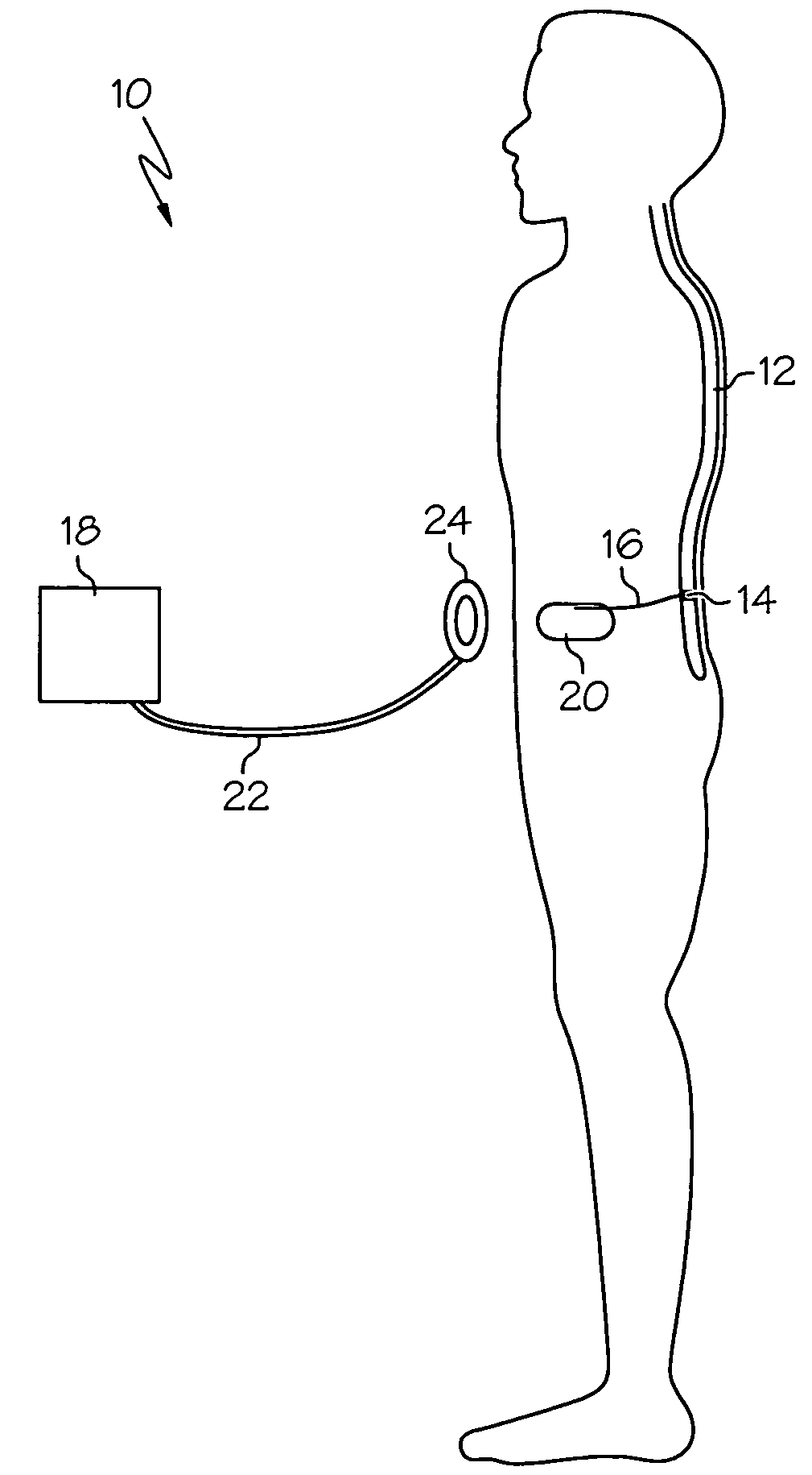
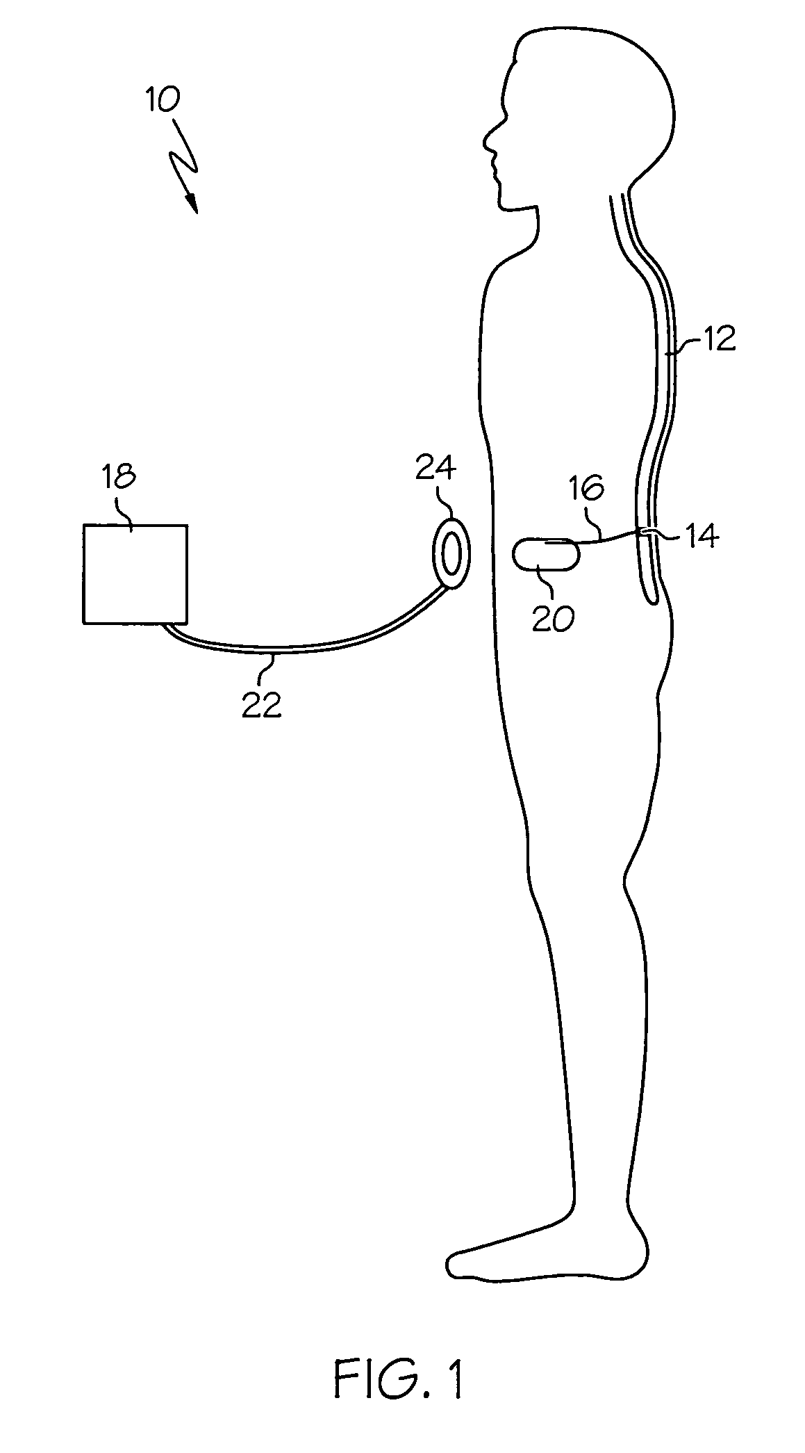
[0047]FIG. 1 is a schematic view of patient 10 having an implant of a neurological stimulation system employing an embodiment of the invention. The preferred system uses a programmer 18 that is coupled via conductor 22 to radio-frequency antenna 24. This permits attending medical personnel to change various stimulation parameters after implant using the radio-frequency communication.

[0048]This communication is directed to an implantable pulse generator 20. The stimulation pulses are produced by implantable pulse generator 20, which is preferably an Itrel II® or Synergy® implantable neurological pulse generator available from Medtronic, Inc.

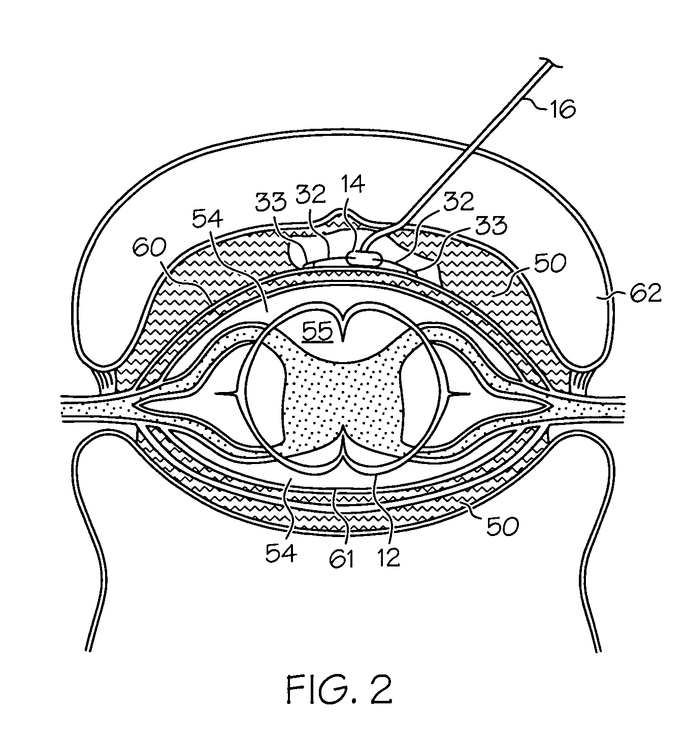
[0049]The stimulation pulses produced by implantable pulse generator 20 are coupled to spinal cord 12 using insulated lead 16, sometimes using also a connecting segment called an extension (not shown). The electrodes of insulated lead 16 are located at its distal end 14 located near the spinal cord 12.

[0050]Though the preferred mode employs fully ...


PUM


Abstract

An implantable lead for electrical stimulation of tissue has wire-like extendable members whose tips curl back upon themselves in open tissue spaces to form 2- or 3-dimensional electrodes. The electrodes may be positioned axially or in other directions from the lead body. Traction on the lead body or extendable members allows easy withdrawal as the member tip electrodes uncurl, allowing removal without major surgery. This apparatus and method is useful for minimally invasive insertion of electrodes or electrode arrays, especially through a narrow body lumen or Tuohy needle, providing therapeutic stimulation of nervous tissue, muscle or organs.

Description

RELATED APPLICATION[0001]This application is a continuation of U.S. patent application Ser. No. 10 / 007,508, filed Nov. 7, 2001, which is hereby incorporated herein by reference in its entirety.FIELD OF THE INVENTION[0002]This invention relates generally to medical devices, and more particularly to particularly to an implantable lead.BACKGROUND OF THE INVENTION[0003]For more than 30 years, electrical stimulation of nervous tissue has been used to control chronic pain. Therapy originates from an implanted source device, called an electric signal generator. The electrical signals, usually a series of brief duration electrical pulses, are delivered through one or more implanted leads that communicate with the source device, and contain several conductive metal electrodes to act as low impedance pathways for current to pass to tissues of interest. For example, in spinal cord stimulation (SCS) techniques, electrical stimulation is provided to precise parts of the human spinal cord through...

Claims


Application Information

Patent Timeline
IPC IPC(8): A61N1/00A61N1/05
CPCA61N1/056
Inventor KING, GARY WILLIAM
Owner MEDTRONIC INC
Learn More