Ion implanter optimizer scan waveform retention and recovery

a technology of ion implanters and optimizers, applied in the field of system and method of ion implantation, can solve the problems of reducing the throughput of ion implanters, and reducing the uniformity of linear scan waves

Inactive Publication Date: 2009-06-16
VARIAN SEMICON EQUIP ASSOC INC
View PDF46 Cites 10 Cited by
  • Summary
  • Abstract
  • Description
  • Claims
  • Application Information

AI Technical Summary

Problems solved by technology

In general, the initial linear scan waveform may not produce a desired uniformity across the semiconductor wafer, and a nonlinear scan waveform may be required.
The setup process is ty...

Method used


Image

  • Ion implanter optimizer scan waveform retention and recovery
  • Ion implanter optimizer scan waveform retention and recovery
  • Ion implanter optimizer scan waveform retention and recovery

Examples


Embodiment Construction

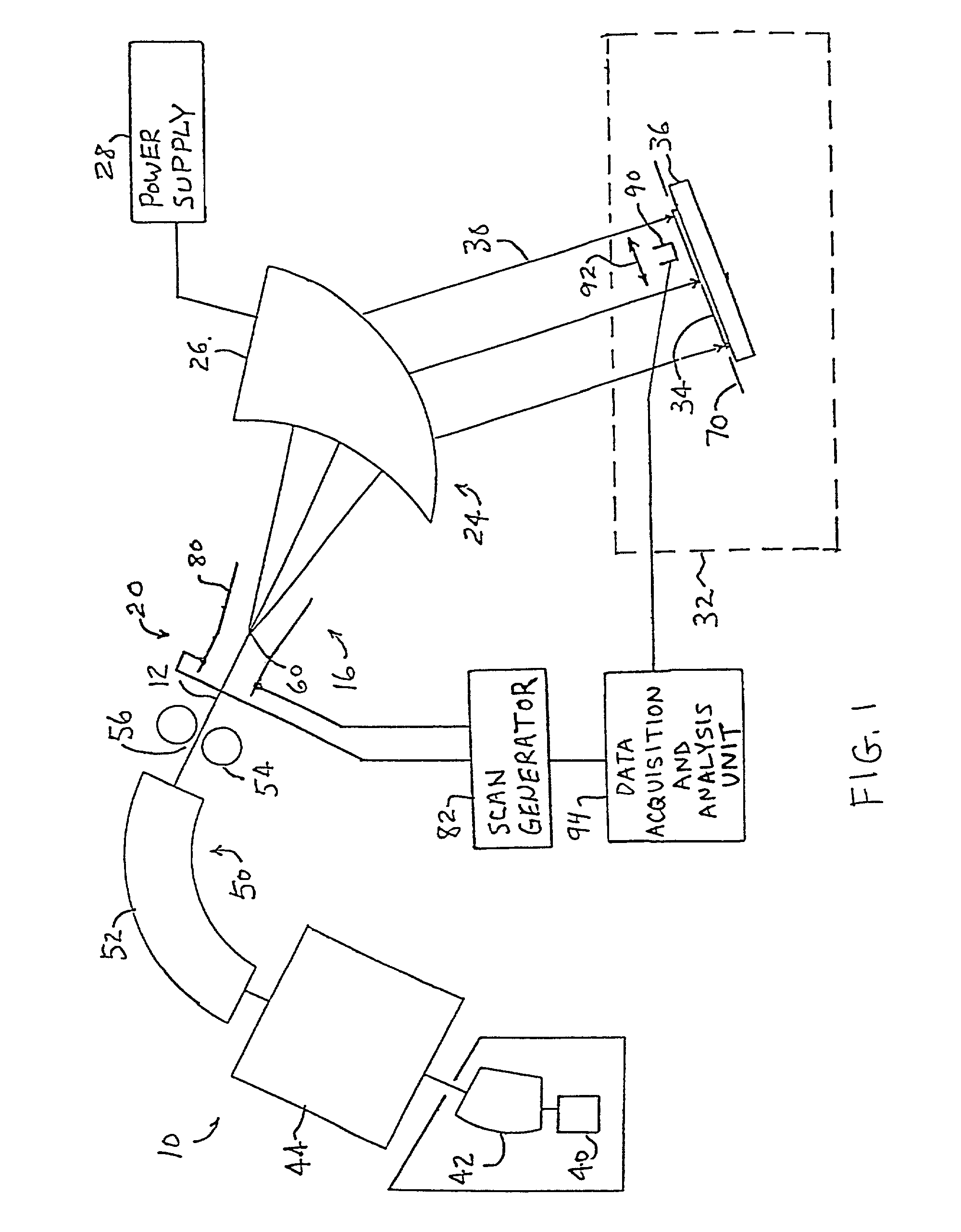
[0019]A simplified block diagram of an example of an ion implanter suitable for incorporating the present invention is shown in FIG. 1. An ion beam generator 10 generates an ion beam of a desired species, accelerates ions in the ion beam to desired energies, performs mass / energy analysis of the ion beam to remove energy and mass contaminants and supplies an energetic ion beam 12 having low levels of energy and mass contaminants. A scanning system 16, which includes a scanner 20 and an angle corrector 24, deflects the ion beam 12 to produce a scanned ion beam 30 having parallel or nearly parallel ion trajectories. An end station 32 includes a platen 36 that supports a semiconductor wafer 34 or other workpiece in the path of scanned ion beam 30 such that ions of the desired species are implanted into the semiconductor wafer 34. The ion implanter may include additional components known to those skilled in the art. For example, the end station 32 typically includes automated wafer handl...


PUM

PropertyMeasurementUnit
Timeaaaaaaaaaa
Currentaaaaaaaaaa
Energyaaaaaaaaaa

Abstract

Methods and apparatus are provided for controlling dose uniformity in an ion implantation system. According to one embodiment of the invention, an initial scan waveform is adjusted to obtain a desired uniformity for use in a first implant process, and the adjusted scan waveform is stored. The stored scan waveform is recalled and used in a second implant process. According to a another embodiment of the invention, desired beam parameters are identified and, based on the desired beam parameters, a stored scan waveform is recalled for use in a uniformity adjustment process, and the uniformity adjustment process is performed. According to a further embodiment of the invention, an apparatus is provided that includes a beam profiler for measuring a current distribution of a scanned ion beam. The apparatus also includes a data acquisition and analysis unit for adjusting an initial scan waveform based on a desired current distribution and the measured current distribution for use in a first implant process, storing the adjusted scan waveform, recalling the stored scan waveform, and using the recalled scan waveform in a second implant process.

Description

CROSS-REFERENCE TO RELATED APPLICATION[0001]This application claims the benefit of provisional application Ser. No. 60 / 232,704 filed Sep. 15, 2000, which is hereby incorporated by reference.FIELD OF THE INVENTION[0002]This invention relates to systems and methods for ion implantation of semiconductor wafers or other workpieces and, more particularly, to methods and apparatus for optimizing the uniformity of a scanned ion beam.BACKGROUND OF THE INVENTION[0003]Ion implantation is a standard technique for introducing conductivity-altering impurities into semiconductor wafers. A desired impurity material is ionized in an ion source, the ions are accelerated to form an ion beam of prescribed energy, and the ion beam is directed at the surface of the wafer. The energetic ions in the beam penetrate into the bulk of the semiconductor material and are embedded into the crystalline lattice of the semiconductor material to form a region of desired conductivity.[0004]Ion implantation systems us...

Claims


Application Information

Patent Timeline
IPC IPC(8): C23C14/54C23C14/48H01J37/147H01J37/317
CPCH01J37/1474H01J37/3171H01J2237/3045
Inventor CUCCHETTI, ANTONELLAOLSON, JOSEPHGIBILARO, GREGORYMOLLICA, ROSARIO
Owner VARIAN SEMICON EQUIP ASSOC INC
Why Eureka
Try Eureka