Charged beam dump and particle attractor

a technology of charge beam and dump, which is applied in the direction of diaphragm, particle separator tube, vacuum evaporation coating, etc., can solve the problems of general constraints on particle contamination associated with waste ion beam, and achieve the effect of reducing particle contamination

Inactive Publication Date: 2009-06-16
AXCELIS TECHNOLOGIES
View PDF7 Cites 12 Cited by
  • Summary
  • Abstract
  • Description
  • Claims
  • Application Information

AI Technical Summary

Benefits of technology

[0011]According to one exemplary aspect of the present invention, a beam dump assembly is provided for reducing contamination of an ion beam in an ion implantation system is provided, wherein the beam dump assembly comprises a particle collector, a particle attractor, and a shield. An electrical potential of the particle attractor is operable to generally attract and slow waste ion beams formed by the ion implantation system, wherein contamination particles associated with the waste ion beams are generally constrained within the particle collector. For example, the electrical potential of the particle attractor is generally opposite of an electrical potential of the ion beam, wherein the waste ion beams are generally attracted to the particle attractor within the particle collector.
[0013]In accordance with the present invention, the particle collector may comprise a generally concave housing, wherein an interior region is generally lined with a carbon-containing material, such as graphite. The lining of the particle collector, for example, is operable to substantially constrain heavier or solid particles associated with the waste ion beams. According to another example, a pump is provided, wherein the pump is in fluid communication with a collection region of the particle collector, wherein gaseous and / or suspended particles within the collector region can be pumped or exhausted out of the beam dump assembly, thus further reducing particle contamination.

Problems solved by technology

However, once waste ion beams enter the particle attractor (via passing through the perforated shield), particle contamination associated with the waste ion beams is generally constrained within the particle collector via the electrical potential difference between the particle attractor and the waste ion beams.

Method used


Image

  • Charged beam dump and particle attractor
  • Charged beam dump and particle attractor
  • Charged beam dump and particle attractor

Examples


Embodiment Construction

[0020]The present invention is directed generally towards systems, apparatuses, and methods for generally mitigating particulate contamination of a workpiece being subjected to an ion beam. Accordingly, the present invention will now be described with reference to the drawings, wherein like reference numerals may be used to refer to like elements throughout. It should be understood that the description of these aspects are merely illustrative and that they should not be interpreted in a limiting sense. In the following description, for purposes of explanation, numerous specific details are set forth in order to provide a thorough understanding of the present invention. It will be evident to one skilled in the art, however, that the present invention may be practiced without these specific details.

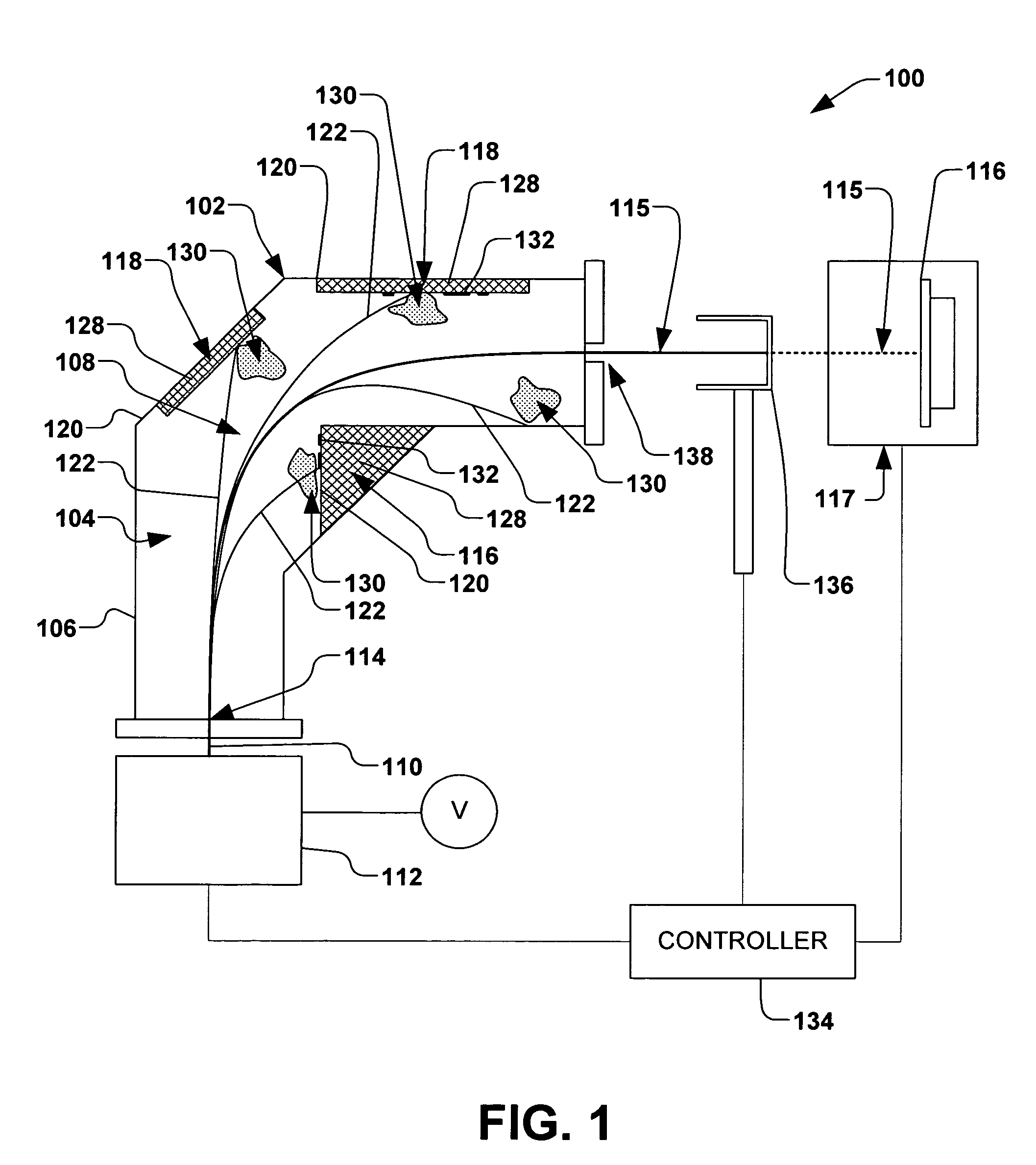
[0021]Referring now to the figures, FIG. 1 illustrates a simplified perspective view of an exemplary ion implantation system 100. It should be noted that the ion implantation system 100 of ...


PUM

PropertyMeasurementUnit
sizeaaaaaaaaaa
electrical potentialaaaaaaaaaa
electrically conductiveaaaaaaaaaa

Abstract

A system, method, and apparatus for mitigating contamination during ion implantation are provided. An ion source, end station, and mass analyzer positioned between the ion source and the end station are provided, wherein an ion beam is formed from the ion source and travels through the mass analyzer to the end station. An ion beam dump assembly comprising a particle collector, particle attractor, and shield are associated with the mass analyzer, wherein an electrical potential of the particle attractor is operable to attract and constrain contamination particles within the particle collector, and wherein the shield is operable to shield the electrical potential of the particle attractor from an electrical potential of an ion beam within the mass analyzer.

Description

REFERENCE TO RELATED APPLICATION[0001]This application claims priority to and the benefit of U.S. Provisional Application Ser. No. 60 / 687,514 which was filed Jun. 3, 2005, entitled PARTICULATE PREVENTION IN ION IMPLANTATION, the entirety of which is hereby incorporated by reference as if fully set forth herein.FIELD OF THE INVENTION[0002]The present invention relates generally to an ion implantation system, apparatus, and method for implanting ions into a workpiece, and more specifically to a system, apparatus, and method for generally preventing particulate contamination associated with an ion beam.BACKGROUND OF THE INVENTION[0003]In the manufacture of semiconductor devices, ion implantation systems are employed to dope a semiconductor wafer or other workpiece with impurities. In such systems, an ion source ionizes a desired dopant element, which is extracted from the source in the form of an ion beam. The ion beam is typically mass analyzed to select ions of a desired charge-to-ma...

Claims


Application Information

Patent Timeline
Patent Type & Authority Patents(United States)
IPC IPC(8): G21K5/10H01J37/08
CPCH01J37/045H01J37/09H01J37/244H01J37/302H01J37/3171H01J2237/022H01J2237/026H01J2237/028H01J2237/30433H01J2237/31705H01J37/08H01J37/304H01J37/317
Inventor VANDERPOT, JOHN W.HUANG, YONGZHANG
Owner AXCELIS TECHNOLOGIES
Why Eureka
Try Eureka