Pin tip attachment structure of conveyor chain for can making

a technology of conveyor chain and canning can, which is applied in the direction of mechanical conveyors, rolling conveyors, packaging, etc., can solve the problems of reducing the quality of drinks bottled in the aluminum can, scratches cannot be prevented from being induced on the inside, and the inside coating of the aluminum can is not perfect, so as to avoid oil and fat adhesion, improve the coating performance, and eliminate scratches

Active Publication Date: 2009-06-23
DAIDO KOGYO CO LTD
View PDF8 Cites 10 Cited by
  • Summary
  • Abstract
  • Description
  • Claims
  • Application Information

AI Technical Summary

Benefits of technology

[0018]According to the pin tip attachment structure of the invention, since the pin tip can be supported while being set on the coil spring even if the pin tip is small, when a container is engaged by the pin tip, the coil spring is compressed and deformed and consequently an impact is mitigated even if the container has a small port, which eliminates scratches induced on the inside of a can or bottle.
[0019]On the other hand, for a can or bottle, it is extremely important to avoid adhesion of oils and fats because the can or bottle will contain drinks, and also when the oils and fats are adhered on the inside of the can or bottle, coating performance of paint becomes worse. However, the pin tip attachment structure of the invention is configured such that the pin is attached with the coil spring or the bushing, and the pin tip can be finally attached. Accordingly, the structure of the invention is advantageous in that the possibility of adhesion of oils and fats to the pin tip is extremely reduced, and consequently adhesion of oils and fats to the inside of a can or bottle is suppressed.

Problems solved by technology

The scratches cause imperfect coating of the inside of the aluminum cans.
As a result, corrosion is induced by bottled drinks, resulting in reduction in quality of the drinks bottled in the aluminum cans 102.
However, while the open edges of the cylinders engaged by such pin tips are not deformed while being conveyed, scratches cannot be prevented from being induced on the inside.
However, such an attachment structure cannot be used for the pin tip 104 having a small size as shown in FIG. 10A.
Therefore, there has been a difficulty that the large pin tip 105 or 109 as shown in FIG. 10B or 10C cannot be used for conveying a bottle or can having a small port, and consequently impact force is exerted between the pin tip and the aluminum can 102 being conveyed, causing scratches on the inside of the can.

Method used


Image

  • Pin tip attachment structure of conveyor chain for can making
  • Pin tip attachment structure of conveyor chain for can making
  • Pin tip attachment structure of conveyor chain for can making

Examples


Embodiment Construction

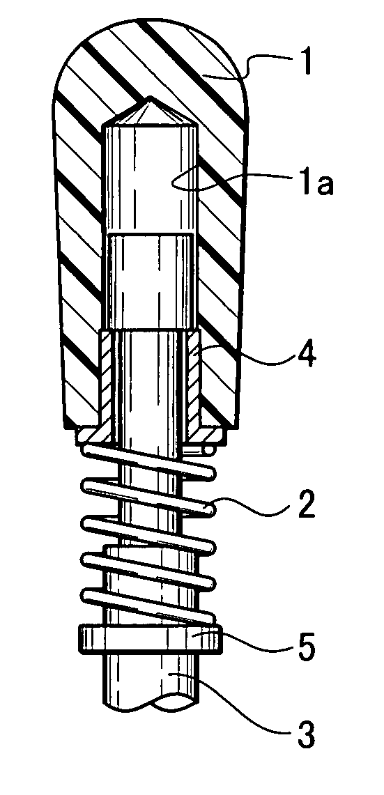
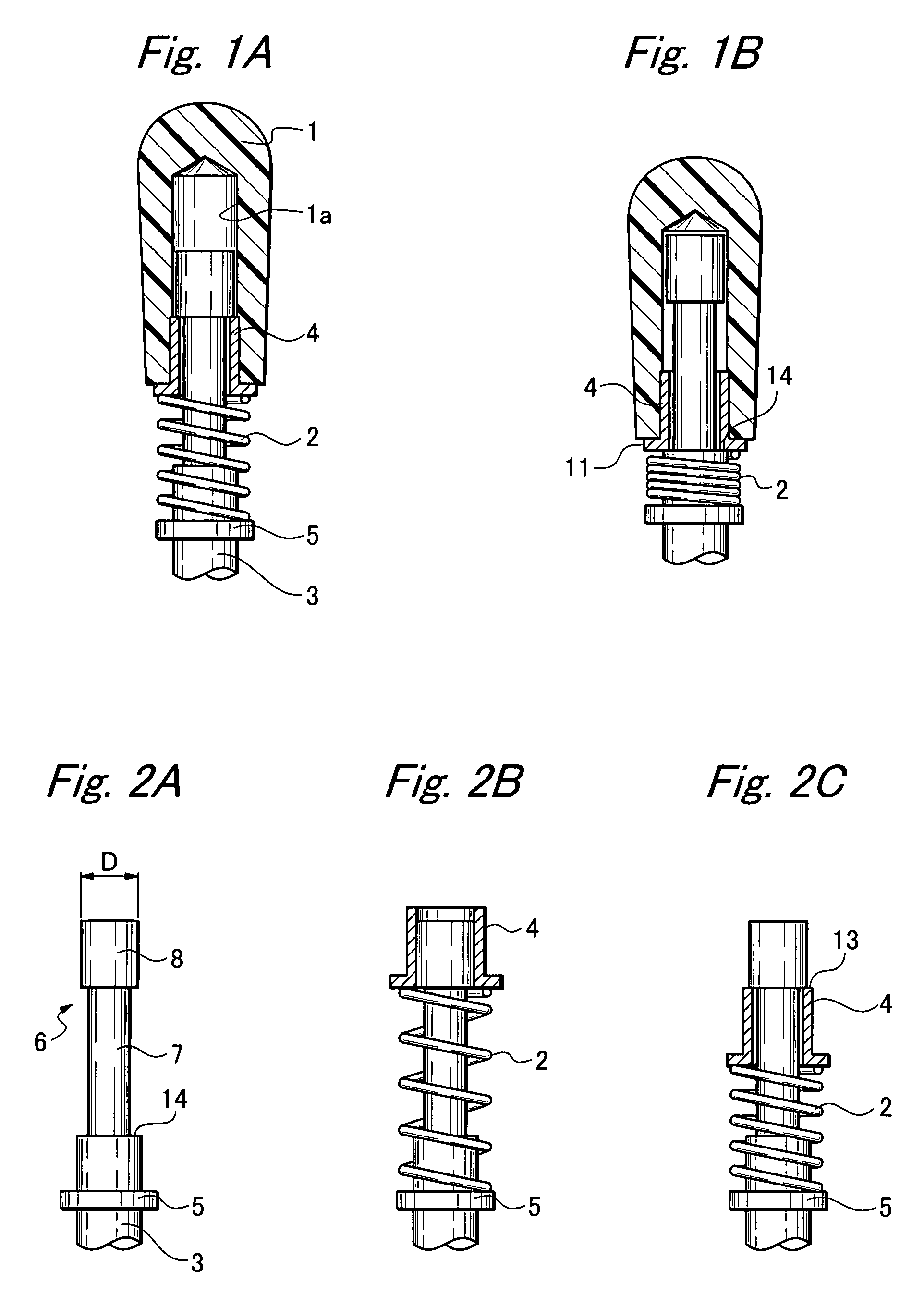
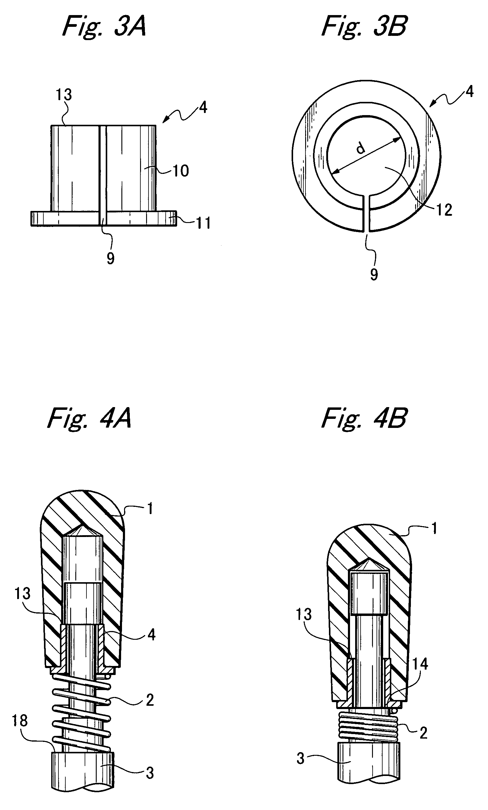
[0030]FIGS. 1A and 1B show a pin tip attachment structure according to a first embodiment of the invention, in which a reference 1 indicates a pin tip, reference 2 indicates a coil spring, reference 3 indicates a pin, reference 4 indicates a bushing with collar, and reference 5 indicates a ring plate, respectively. The pin tip 1 is attached to the pin 3 in a stretchable and contractible manner by the coil spring 2 mounted on the pin 3. FIG. 1A shows a case that the coil spring 2 is stretched and the pin tip 1 is therefore in a raised (or extended) position, and FIG. 1B shows a case that the coil spring 2 is compressed and deformed and the pin tip 1 is therefore in a lowered (or contracted) position.

[0031]The pin tip 1 has a front end side formed in a semispherical shape, and has a cylindrical hole 1a opened at a lower end side in which the bushing 4 is fitted. At a front end portion 6 of the pin 3, a thinned small-diameter portion 7 is formed, and a large diameter portion 8 having t...


PUM


Abstract

To provide a pin tip attachment structure that can engage a container with a bottom, such as a can or bottle, and convey the container without scratching it, a small diameter portion having a predetermined length is formed at a front end portion of a pin. A bushing is fitted in a lower end portion of a cylindrical hole of a pin tip having the cylindrical hole opened at a lower end side, and the bushing is vertically movably inserted onto the small diameter portion of the pin. A stopper portion for retaining the bushing is provided at a front end of the small diameter portion. A spring receiver portion is provided below the small diameter portion, and a coil spring is provided in a compressible manner between the spring receiver portion and the bushing or the lower end of the pin tip.

Description

BACKGROUND OF THE INVENTION[0001]1. Field of the Invention[0002]The present invention relates to a structure for stretching a pin of a chain and attaching a pin tip to an end of the pin, the chain being for engaging and conveying a container with a bottom, such as a can or bottle.[0003]2. Related Art[0004]Recently, aluminum or steel cans have been often used for containers of drinks such as beer or juice. A large number of the cans are manufactured and bottled with drinks in factories. When the cans are manufactured, many steps such as a step of printing on an outer circumferential face, a step of drying, and a step of coating the inside are necessary. In each of the steps, the cans are conveyed by a pin chain conveyor. FIG. 9 shows aluminum cans 102 being conveyed while being engaged by pin tips 101 of a pin chain conveyor 100. Of course, steel cans are conveyed in the same way.[0005]Speed of the aluminum cans 102 being conveyed while being engaged by the pin tips 101 of the pin ch...

Claims


Application Information

Patent Timeline
Patent Type & Authority Patents(United States)
IPC IPC(8): B65G17/12
CPCB65G17/32B65G2207/38B65G17/02
Inventor SOURI, YUKIOSAKAGUCHI, SHUJI
Owner DAIDO KOGYO CO LTD
Why Eureka
Try Eureka