Optical transmission device and light-receiving module

a technology of optical transmission device and light-receiving module, which is applied in the direction of optical waveguide light guide, instruments, nanotechnology, etc., can solve the problems of difficult coupling as compared with the conventional general waveguide, and achieve the effect of convenient fabrication

Inactive Publication Date: 2009-06-30
PANASONIC CORP
View PDF7 Cites 38 Cited by
  • Summary
  • Abstract
  • Description
  • Claims
  • Application Information

AI Technical Summary

Benefits of technology

[0019]The present invention is directed, to provide the optical transmission device and the light-receiving module, easy to fabricate and which can be coupled with the incident beam with the large diameter to guide the light to the arbitrary light-receiving position.
[0039]Since the first optical member has the negative refraction angle and the second optical member has the positive refraction angle, an entered diffused beam is propagated while condensed in the first optical member and diffused in the second optical member in a configuration where they are aligned in tandem alternatively. The optical path length for condensation can be set longer than the optical path length for diffusion by differentiating the thicknesses of the first and second optical members, so that a beam diameter can be made smaller as the beam is propagated within the optical transmission device. Along therewith, an axial misalignment at an outgoing position can be made smaller even when an incident light is angularly misaligned.
[0054]According to the present invention, there can be provided the optical transmission device and the light-receiving module, easy to fabricate and which can be coupled with the incident beam with the large diameter to guide the light to the arbitrary light-receiving position.

Problems solved by technology

However, in such a photonic crystal waveguide 100, an incident beam diameter, which allows the beam to be coupled at an incident side in a similar manner to that of the conventional channel waveguide, is limited and a channel width is made to 1 μm or less within a defective width of one to two cycles, so that it is difficult to be coupled as compared with the conventional general waveguide.

Method used


Image

  • Optical transmission device and light-receiving module
  • Optical transmission device and light-receiving module
  • Optical transmission device and light-receiving module

Examples


first embodiment

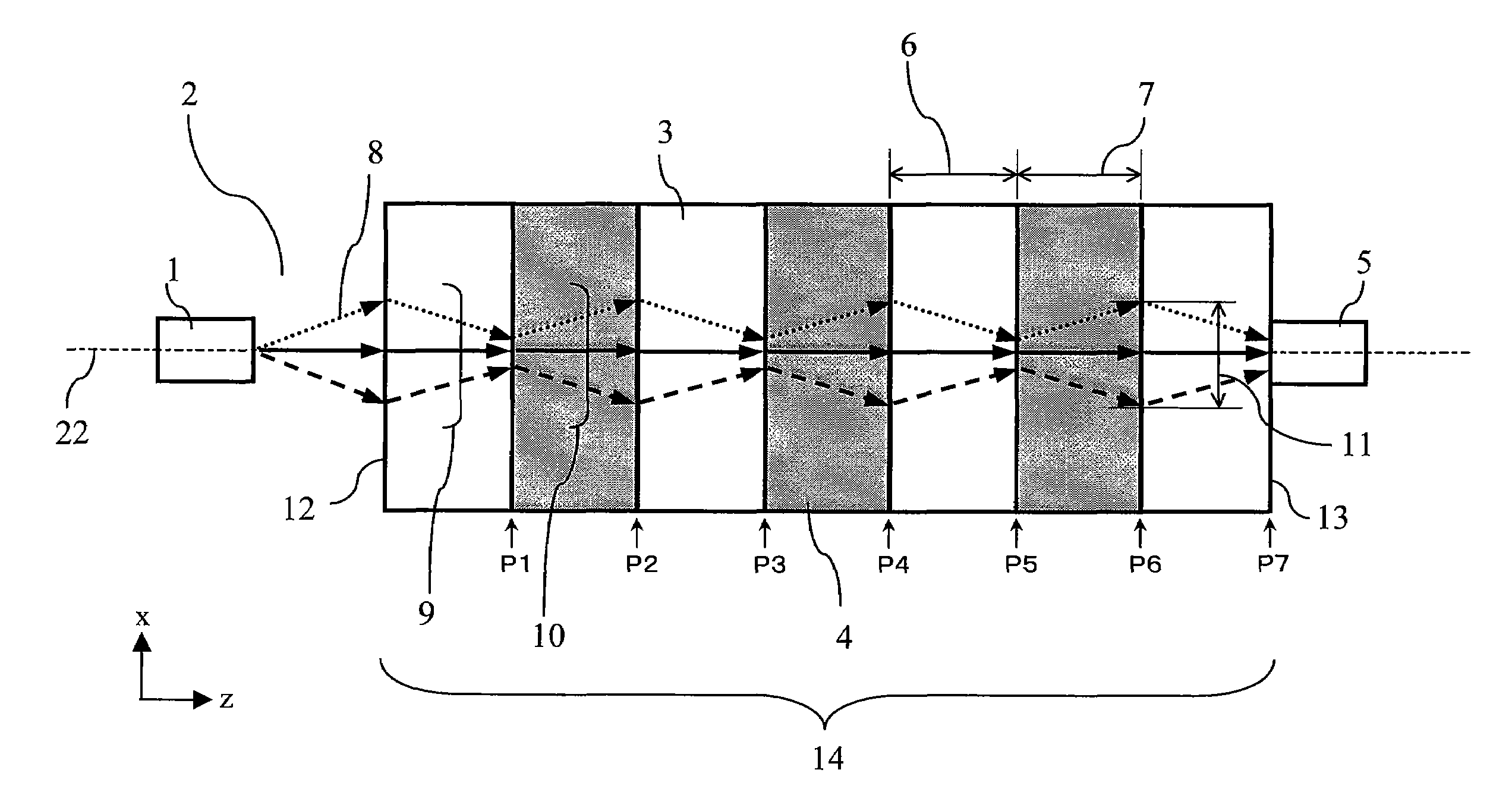
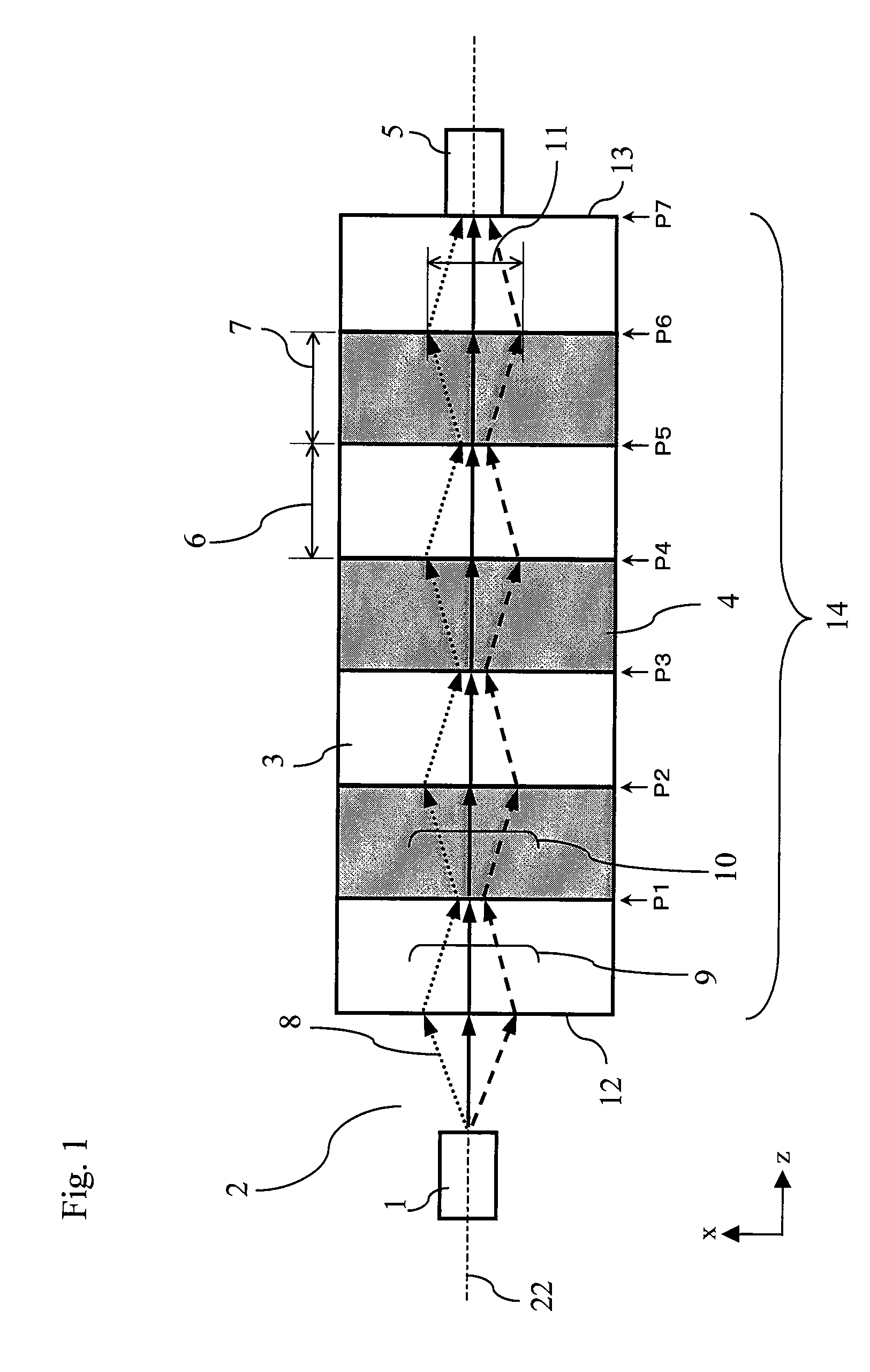
[0111]FIG. 1 illustrates a schematic configuration diagram of a light-receiving module according to a first embodiment of the present invention.

[0112]The configuration and operation of the light-receiving module of the first embodiment are described hereinbelow by primarily referring to FIG. 1.

[0113]The light-receiving module of the first embodiment is provided with a transmission section 14 and a light-receiving section 5.

[0114]The transmission section 14 is provided with a plurality of negative refractive index photonic crystals 3 having a negative refraction angle with respect to an incident angle of an incident light 8 from a light source 1 isolated by a free space 2 and a plurality of positive refractive index photonic crystals 4 having a positive refraction angle with respect to the incident angle. The negative and positive refractive index photonic crystals 3 and 4 are arranged in tandem alternatively on an optical axis 22 of the transmission section 14 so that the negative r...

second embodiment

[0139]FIGS. 3 and 4 illustrate schematic configuration diagrams of the light-receiving module according to a second embodiment of the present invention. FIG. 3 illustrates the case where the incident light is not angularly misaligned, and FIG. 4 illustrates the case where the incident light enters while being angularly misaligned. In the respective drawings, like reference numerals denote like components as those in FIG. 1.

[0140]The configuration and operation of the light-receiving module of the second embodiment are described hereinbelow by primarily referring to FIGS. 3 and 4.

[0141]As compared to the light-receiving module of the first embodiment where the negative and positive refractive index photonic crystals 3 and 4 having the same optical path length are arranged in tandem alternatively, the light-receiving module of the second embodiment is different in that negative refractive index photonic crystals 23 and positive refractive index photonic crystals 24 with varying thickn...

third embodiment

[0154]FIG. 5 illustrates a schematic configuration diagram of the light-receiving module according to a third embodiment of the present invention. Like reference numerals denote like components as those in FIG. 1.

[0155]The configuration and operation of the light-receiving module of the third embodiment are described hereinbelow by primarily referring to FIG. 5.

[0156]The light-receiving module of the third embodiment is provided with a transmission section 49 and the light-receiving section 5.

[0157]The transmission section 49 is provided with a plurality of graded negative refractive index photonic crystals 17 having the negative refraction angle and a plurality of graded positive refractive index photonic crystals 18 having the positive refraction angle, which are arranged in tandem alternatively on the optical axis 22 of the transmission section 49 so that the graded negative refractive index photonic crystals 17 are disposed at both an incident end 47 and an outgoing end 48. The ...


PUM


Abstract

An optical transmission device is provided with a first optical member having a negative refraction angle with respect to an incident angle of a beam and a second optical member having a positive refraction angle with respect to the incident angle, wherein the first and second optical members are arranged one each or more in tandem alternatively.

Description

BACKGROUND OF THE INVENTION[0001]1. Field of the Invention[0002]The present invention relates to an optical transmission device and a light-receiving module which can be used with a waveguide or the like for transmitting lights.[0003]2. Related Art of the Invention[0004]Examples of a waveguide which transmits lights include a channel waveguide which provides a refractive index difference or a reflection portion in the nonparallel direction, e.g., the perpendicular direction, to an optical axis to transmit the lights by repetition of total reflection or partial reflection and a bulk waveguide which provides a plurality of lenses or mirrors on the optical axis to transmit the lights by performing beam conversion. Note herein that the case where the lights are coupled by a single lens or mirror is classified as the bulk waveguide for convenience.[0005]In addition, researches on an optical waveguiding using a photonic band of a photonic crystal of which a refractive index is modulated i...

Claims


Application Information

Patent Timeline
Patent Type & Authority Patents(United States)
IPC IPC(8): G02B27/30
CPCB82Y20/00G02B6/1225G02B6/29361
Inventor HAMADA, HIDENOBU
Owner PANASONIC CORP
Why Eureka
Try Eureka