

Honeycomb structure
a honeycomb and ceramic structure technology, applied in the field of honeycomb structure, can solve the problems of cracks and soot in the honeycomb structure, harmful to the environment or to human bodies, and the soot contained in the exhaust gas discharged from the internal combustion engine of vehicles such as buses or trucks, etc., and achieve the effect of large effect, small heat capacity of the honeycomb structure using the porous ceramic members, and not lowering the characteristic of temperature ris
Active Publication Date: 2009-07-07
IBIDEN CO LTD
View PDF27 Cites 34 Cited by
- Summary
- Abstract
- Description
- Claims
- Application Information
AI Technical Summary
Benefits of technology
The present invention provides a honeycomb structure that prevents cracks and failure of the structure or adhesive layer, even when the porosity or thickness of the cell walls is high. The honeycomb structure satisfies a specific relationship between the apparent density of the porous ceramic members and the Young's modulus of the adhesive layer. This relationship helps to relax the thermal stress generated in the honeycomb structure and prevent failure. The honeycomb structure can be used in various applications such as filters, exhaust gas systems, and construction equipment.
Problems solved by technology
Recently, it has been a problem that particulates such as soot contained in exhaust gas discharged from internal combustion engines of vehicles such as, for example, engines in buses or trucks, construction machines, etc. are harmful to the environment or to human bodies.
As a result, thermal stress generated in the honeycomb structure may increase so that there a crack may occur in the honeycomb structure.
This lowering of the strength also causes a crack in the honeycomb structure.
Method used
View moreImage
Smart ImageViewing Examples

Examples
example 1
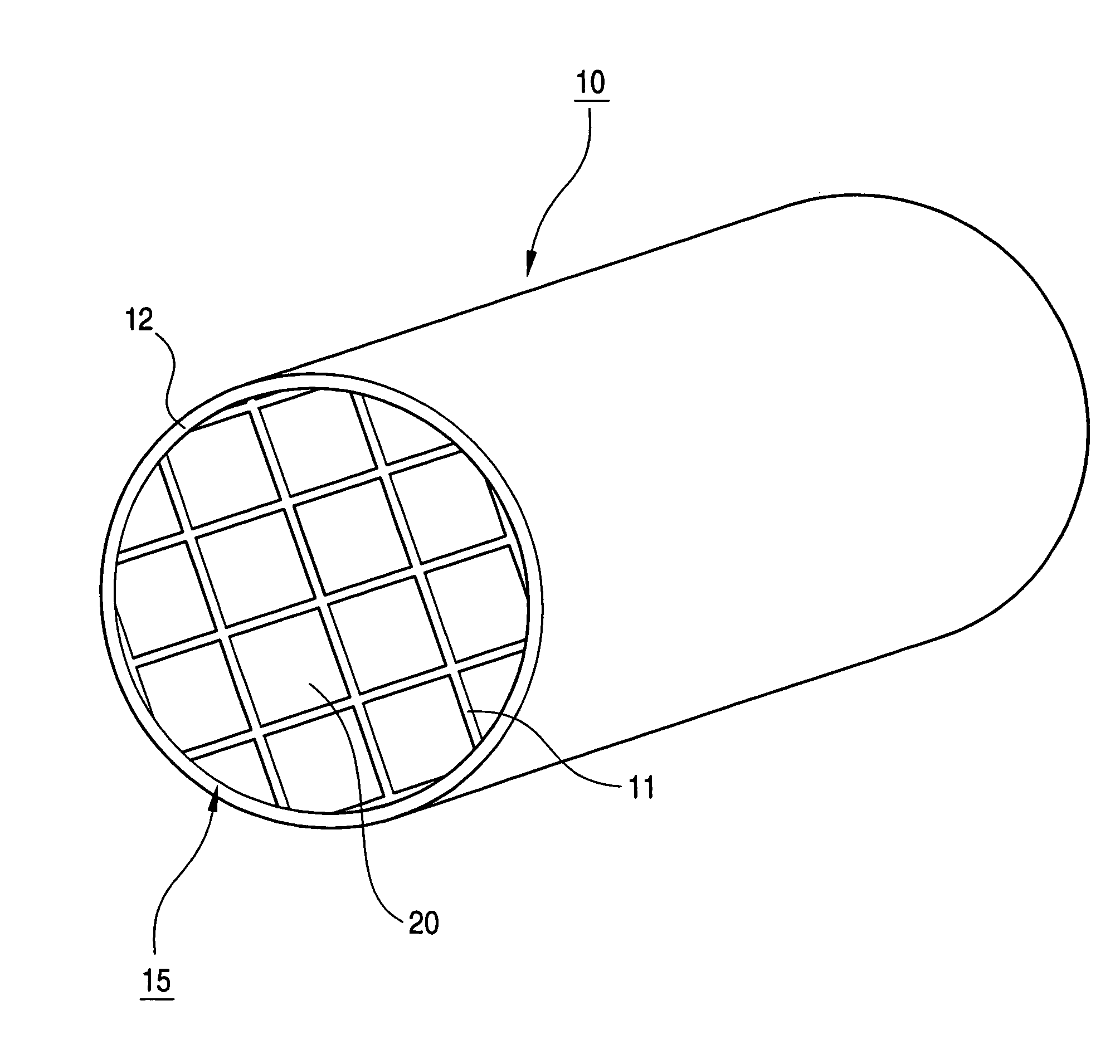
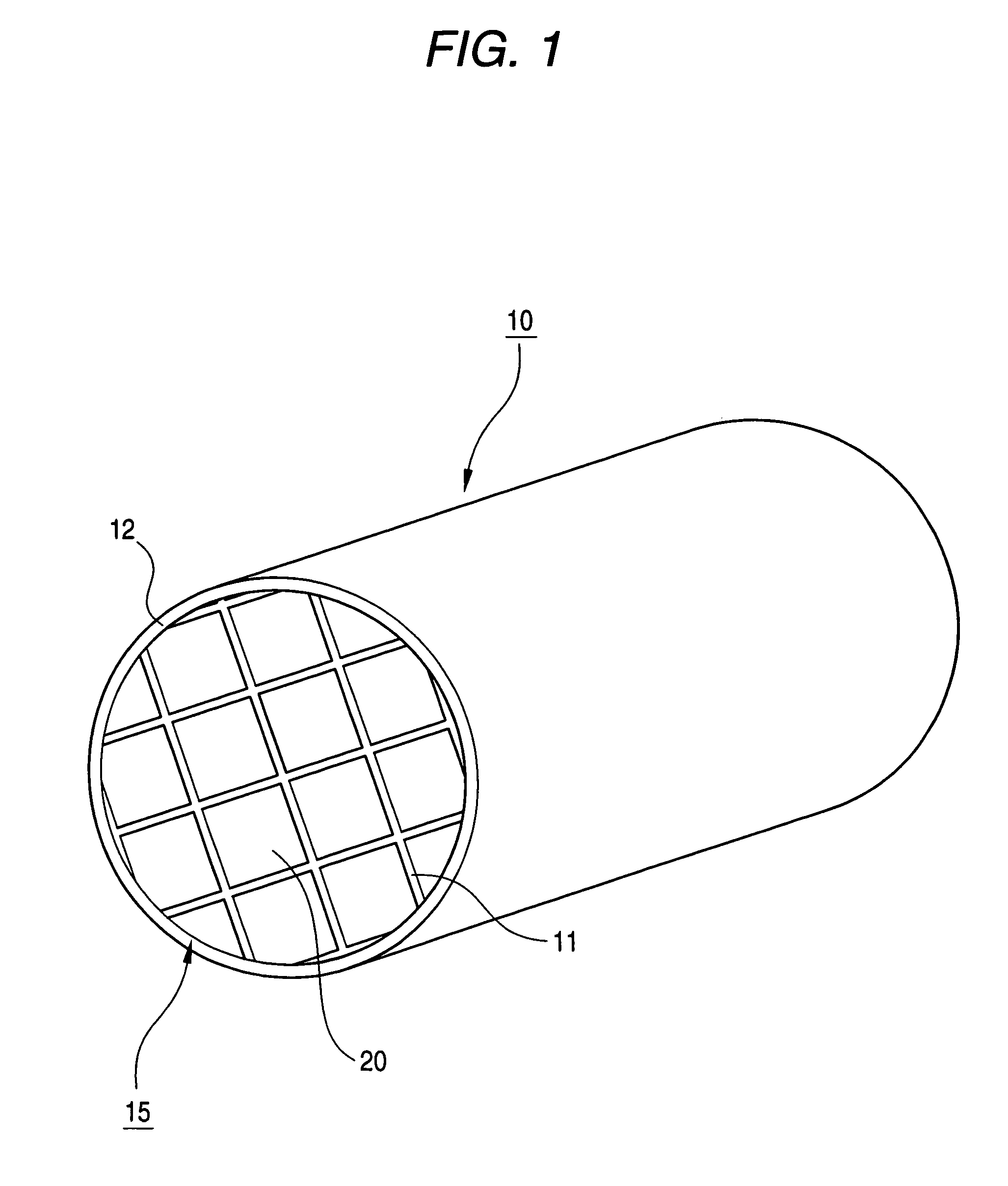
[0125]Using the adhesive paste B as an adhesive layer 2 mm thick, 16 (4 by 4) porous ceramic members A were bonded and successively cut by a diamond cutter. Thus, a cylindrical ceramic block 15 (see FIG. 1) was produced.
[0126]Next, the adhesive paste B was used as a coat forming paste and applied to the outer circumferential portion of the ceramic block 15 so as to be 0.5 mm thick, and then dried at 120° C. Thus, a cylindrical honeycomb structure 10 measuring 143.8 mm in diameter and 150 mm in length was manufactured.
Login to View More PUM
| Property | Measurement | Unit |
|---|---|---|
| apparent density | aaaaa | aaaaa |
| apparent density | aaaaa | aaaaa |
| pore size | aaaaa | aaaaa |
Abstract
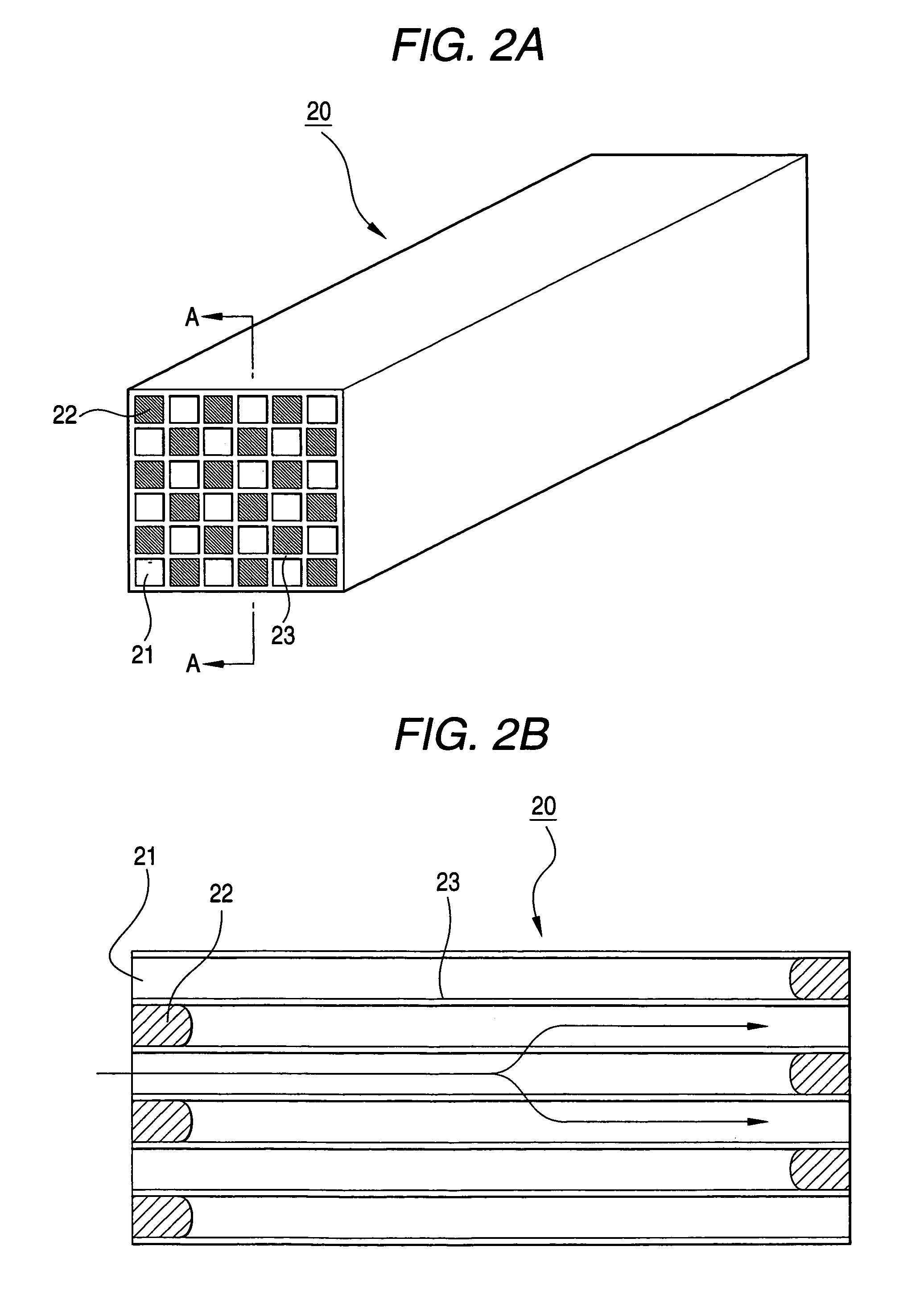
A honeycomb structure including a plurality of porous ceramic members which are bonded through an adhesive layer, each of the porous ceramic members has a plurality of cells, which are arranged in parallel while being separated by cell walls. The cells extend in a longitudinal direction of the honeycomb structure. In the honeycomb structure, the following relationship is satisfied:2≦B≦100 / 3×A−10 / 3 (1)where A (g / cm3) designates apparent density of the porous ceramic members, and B (GPa) designates Young's modulus of the adhesive layer.
Description
CROSS-REFERENCE TO RELATED PATENT APPLICATIONS[0001]The right of priority under 35 U.S.C. §119(a) is claimed based on Japanese Patent Application No. 2005-112254, filed Apr. 8, 2005, the entire disclosure of which is hereby incorporated by reference.BACKGROUND OF THE INVENTION[0002]1. Field of the Invention[0003]The present invention relates to a honeycomb structure which may serve, for example, as a filter for collecting and removing particulates etc. in exhaust gas discharged from an internal combustion engine such as, for example, a diesel engine.[0004]2. Description of the Related Art[0005]Recently, it has been a problem that particulates such as soot contained in exhaust gas discharged from internal combustion engines of vehicles such as, for example, engines in buses or trucks, construction machines, etc. are harmful to the environment or to human bodies.[0006]Therefore, there have been proposed various filters using honeycomb structures made of porous ceramics for collecting ...
Claims
Login to View More Application Information
Patent Timeline
 Patent Type & Authority Patents(United States)
IPC IPC(8): B01D46/00F01N3/022
CPCB01D39/2093B01D46/2429B01D46/2448B01D53/885B01J35/04F01N3/0222F01N3/035Y10T428/24149B01D46/2459B01D46/247B01D2046/2433B01D2046/2496B01J23/42B01J37/0215F01N2330/06F01N2450/28Y10S55/05Y10S264/48Y10S55/30Y10S55/10B01D46/2425B01D46/24491B01D46/2498B01D46/24492B01D46/24495B01J35/57B01D46/2474B01J35/56
Inventor KUNIEDA, MASAFUMI
Owner IBIDEN CO LTD