System with user interface for network planning and mobility management optimization in a mobile communication network and method thereof

a mobile communication network and user interface technology, applied in the field of user interfaces, can solve the problems of wasting resources, system cannot maintain the approximate location of each subscriber, and the parameters employed in mobility management are difficult to be defined in an optimal manner, so as to achieve the effect of optimizing mobility managemen

Active Publication Date: 2009-07-14
GROUNDHOG INC
View PDF6 Cites 35 Cited by
  • Summary
  • Abstract
  • Description
  • Claims
  • Application Information

AI Technical Summary

Benefits of technology

[0009]In accordance with exemplary embodiments of the present invention, the above-identified deficiencies and drawbacks for use in analyzing the status of a mobile network and thereby optimizing mobility management for the live mobile network are overcome. The present invention provides a system and method for performing a network planning and mobility management optimization in a mobile communication network through a GUI. The application GUI window allows users to operate required procedures for network planning and mobility management optimization.
[0013]Then, users can easily perform the network planning and the mobility management optimization through a graphic user interfaces, and they can analyze the planning result to determine an optimal plan which meets customer's requirements (e.g. reducing signaling congestion, improving inter Base Station Controller (BSC) / Mobile Switching Center (MSC) handover failures, better network responsiveness, and a higher quality of service, etc.). Additionally, the reporting mechanism of the invention allows various rendering forms such as viewing on screen, printing to spreadsheets or sending the report via email.

Problems solved by technology

Since subscribers are free to move within the service area of the system, the system can only maintain the approximate location of each subscriber.
Because there are many tradeoffs and complexity involved, the parameters employed in mobility management are difficult to be defined in an optimal manner.
For example, how to define the scope, including the size and the border, of location areas so as to decrease the overall traffic loads of the mobile communication network is an important issue for optimizing mobility management.
However, the system must waste its resources by performing frequently location area updates, and the mobile station must waste its power to transmit the location area update signal.
Alternatively, if the size of the location area is too large, mobile stations cross the border of the location area rarely and do not perform location area updates frequently.
However, a large coverage area has to be paged when a call or a message arrives, and thereby the resources of the system are wasted.
Furthermore, the subscribers may cross the border of a specific location area back and forth, thereby causing many location area updates, if the border of the location area is not properly set.
As a result, the system wastes its resources by processing frequent location area update procedures, and the mobile stations waste power transmitting the location area update signal.
Those conventional mobility models most likely are used to study issues for subscribers' behavior, as mentioned, not for the purpose of mobility management optimization in a live mobile communication network so that they are deficient in precision and accuracy to practically optimize a mobility management.
Moreover, the methods and models described above don't provide suitable and user-friendly software for users, basically, the user interface thereof is merely for the purpose of engineering-background people to use.

Method used


Image

  • System with user interface for network planning and mobility management optimization in a mobile communication network and method thereof
  • System with user interface for network planning and mobility management optimization in a mobile communication network and method thereof
  • System with user interface for network planning and mobility management optimization in a mobile communication network and method thereof

Examples


Embodiment Construction

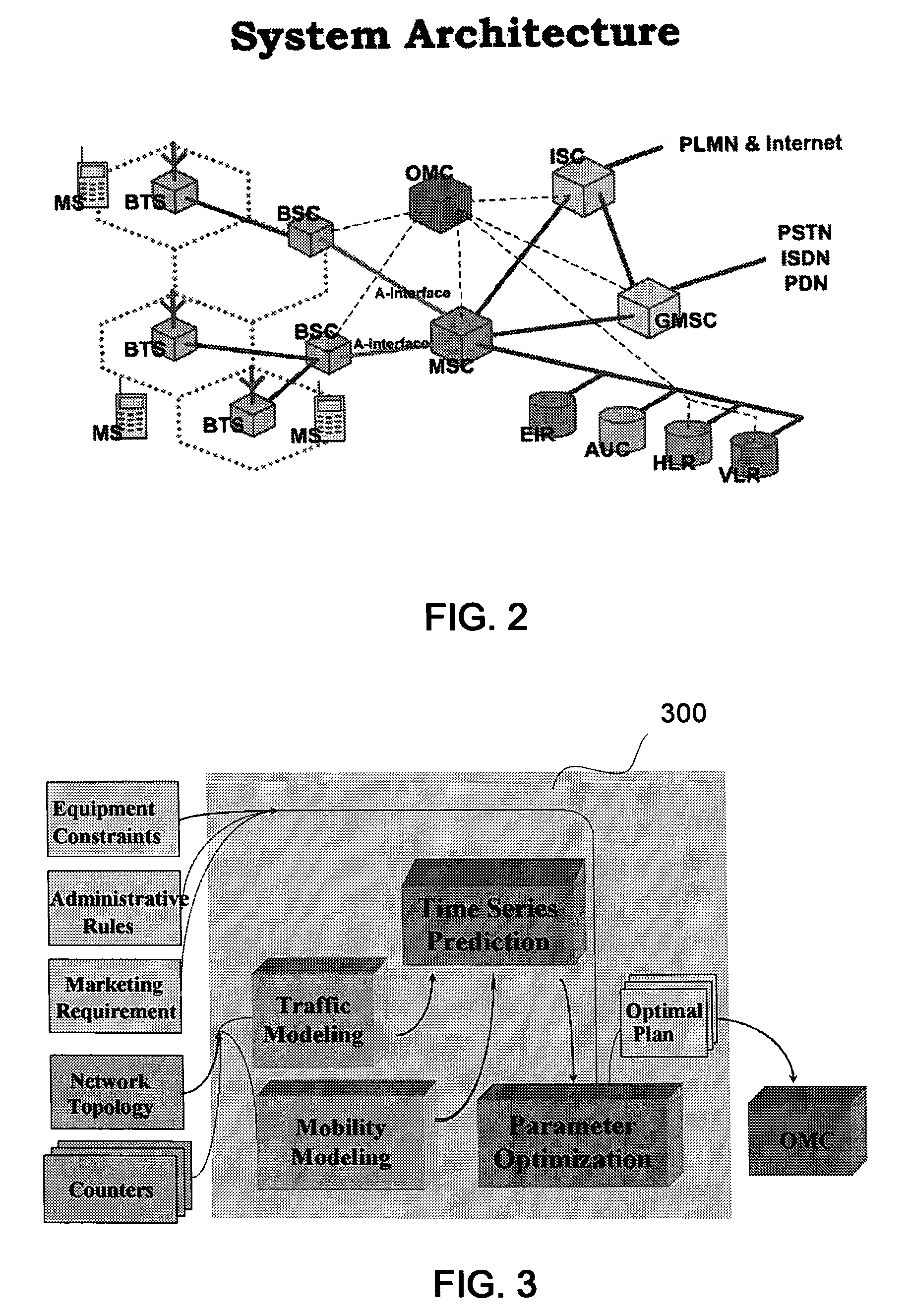
[0026]The system architecture of a mobile communication network is shown in FIG. 2. The basic layout of the system architecture in terms of several functional entities, whose functions and interfaces are specified, will be described as follows.

[0027]The Public Land Mobile Network (PLMN) includes the following system entities: The Mobile Station (MS) represents the terminal equipment used by the wireless subscriber in a mobile communication network. The Base Transceiver Station (BTS) is the base station serving one cell of the system. The Base Station Controller (BSC), controlling one or more Base Transceiver Stations, is responsible for communication within a location area / routing area. Operation and Maintenance Center (OMC) allows the network provider to operate, administer, and monitor the functioning of the system, and update equipment and subscriber databases. Mobile Switching Center (MSC) performs the switching functions for all mobile stations located in the geographic area co...


PUM


Abstract

A system and method for performing a network planning and mobility management optimization is provided, and it includes a graphical user interface (GUI) front-end for allowing users to operate required procedures for network planning and mobility management optimization. According to this invention, the network plan takes a network topology (NT) and its associated network statistic data as input. Accordingly, a network plan can represent an arrangement of network elements which display a superior-subordinate relationship between network elements in the mobile communication network. Moreover, the network plan comprises a plurality of statistic data reflecting a plurality of user mobility behaviors and a plurality of traffic behaviors of network elements in the mobile communication network. Moreover, network elements, links and their related statistics data can be presented on the GUI window, and then users can analyze traffic conditions and the planning result to determine an optimal plan which meets the optimization level required.

Description

CROSS REFERENCE TO OTHER APPLICATIONS[0001]This application claims the benefit of U.S. Provisional Patent Application, Ser. No. 60 / 517,861, entitled “System and User Interface for Network Planning, Mobility Management, and Mobility Management Optimization In A Wireless Communication System” filed on Nov. 07, 2003, and U.S. Provisional Patent Application, Ser. No. 60 / 601,618, entitled “User Interface of Mobility Management Optimization In 3D with features such as dot size representing mobility volume, etc” filed on Aug. 16, 2004 are incorporated by reference herein.[0002]This application is a continuation-in-part of application, “SYSTEM FOR CONSTRUCTING A MOBILITY MODEL FOR USE IN MOBILITY MANAGEMENT IN A WIRELESS COMMUNICATION SYSTEM AND METHOD THEREOF”, Ser. No. 10 / 369,678, filed on Feb. 21, 2003, published. No. US-2004-0165561-A1, published on Aug. 26, 2004 is hereby incorporated the content of this application by reference.FIELD OF THE INVENTION[0003]The invention relates general...

Claims


Application Information

Patent Timeline
Patent Type & Authority Patents(United States)
IPC IPC(8): H04W24/00H04W16/18
CPCH04W16/18H04Q3/0083
Inventor CHIOU, TA-GANGYEH, CHUN-CHIHJUANG, ZI-JINGYOUNG, MING-HUI
Owner GROUNDHOG INC
Why Eureka
Try Eureka