Hydraulic regenerative braking system for a vehicle

a technology of hydraulic regenerative braking and vehicle, which is applied in the direction of braking systems, mechanical equipment, transportation and packaging, etc., can solve the problems of not being able to easily package in automotive passenger vehicles, heavy and expensive, and large volume, and achieve the effect of conserving spa

Inactive Publication Date: 2009-07-21
WALKER FRANK H
View PDF46 Cites 23 Cited by
  • Summary
  • Abstract
  • Description
  • Claims
  • Application Information

AI Technical Summary

Benefits of technology

[0009]Accordingly, the present invention provides a hydraulic regenerative braking system that can conserve space by using fixed displacement, or limited variable displacement, pump-motors.
[0010]The invention also provides a hydraulic regenerative braking system that uses a hydraulic transformer to effect changes in fluid pressure within the system, thereby eliminating the need for a variable displacement pump-motor.
[0011]The invention further provides a hydraulic pump-motor that includes a cam for actuating the pistons, where the cam is disposed inboard of the pistons, thereby conserving space by providing a smaller pump-motor.
[0012]The invention also provides a hydraulic regenerative braking system for a vehicle. The system includes at least one hydraulic machine operable as a pump configured to be driven by energy received from at least one vehicle wheel when the vehicle is braking, thereby facilitating storage of vehicle braking energy. The at least one hydraulic machine is further operable as a motor configured to be driven by stored braking energy, thereby providing torque to at least one vehicle wheel. A first accumulator is configured to receive fluid from the at least one hydraulic machine, and to store the fluid under pressure. The first accumulator is further configured to provide pressurized fluid to the at least one hydraulic machine, thereby facilitating use of the hydraulic machine as a motor. A second accumulator is configured to store pressurized fluid and to provide a charge pressure to an inlet of the at least one hydraulic machine. A variable ratio transformer is in communication with the first and second accumulators and the at least one hydraulic machine. The transformer is operable to vary the pressure of the pressurized fluid provided to the at least one hydraulic machine, thereby facilitating variation in the torque provided to the at least one vehicle wheel. The transformer is further operable to vary the pressure of the fluid received by the first accumulator. A control module is configured to receive inputs related to operation of the vehicle, and to control operation of the transformer. The inputs include an acceleration request and a braking request.
[0013]The invention further provides a hydraulic machine operable as a pump configured to be driven by a rotating shaft, thereby increasing the pressure of fluid flowing through the pump. The hydraulic machine is further operable as a motor configured to be driven by pressurized fluid, thereby providing torque to a shaft. The hydraulic machine includes a housing, including a high pressure fluid port and a low pressure fluid port. The hydraulic machine also includes a plurality of radial pistons. Each of the pistons is configured to reciprocate within a corresponding cylinder in the housing, thereby pumping fluid when the hydraulic machine is operating as a pump, and providing torque when the hydraulic machine is operating as a motor. Each of the pistons includes a corresponding cam follower. A cam is disposed within the housing, and has a plurality of external lobes configured to cooperate with the cam followers to translate rotational motion of the cam into linear motion of the pistons when the hydraulic machine is operating as a pump, and to translate linear motion of the pistons into rotational motion of the cam when the hydraulic machine is operating as a motor. The cam includes an aperture therethrough for receiving a rotatable shaft. A rotatable valve plate has a plurality of apertures therethrough; at least some of the apertures communicate with the high pressure fluid port and at least some of the apertures communicate with the low pressure fluid port. The valve plate is configured to provide a fluid path between the cylinders and the high pressure fluid port when corresponding pistons are in a power stroke and between the cylinders and the low pressure fluid port when corresponding pistons are in an exhaust stroke, thereby facilitating operation of the hydraulic machine as a motor. The valve plate is further configured to provide a fluid path between the cylinders and the high pressure fluid port when corresponding pistons are in an exhaust stroke and between the cylinders and the low pressure fluid port when corresponding pistons are in a power stroke, thereby facilitating operation of the hydraulic machine as a pump.
[0015]The invention further provides a compact hydraulic machine operable as a pump and a motor, and configured to be disposed on a vehicle driving shaft proximate a vehicle wheel. The hydraulic machine includes a housing which has a first housing portion, a second housing portion, and an outer ring. The first housing portion includes a high pressure fluid port and a low pressure fluid port. The second housing portion includes a plurality of radially oriented cylinders disposed therein, and the outer ring includes a tapered bore to facilitate sealing of each of the cylinders. The hydraulic machine also includes a plurality of pistons, each of which includes a cam follower, and each of which is configured to reciprocate within a corresponding cylinder. A cam is disposed within the housing, and has a plurality of external lobes configured to cooperate with the cam followers to translate rotational motion of the cam into linear motion of the pistons when the hydraulic machine is operating as a pump, and to translate linear motion of the pistons into rotational motion of the cam when the hydraulic machine is operating as a motor. The cam includes an aperture therethrough for receiving a rotatable shaft. A rotatable valve plate has a plurality of apertures therethrough, and is configured to selectively connect the cylinders with the low and high pressure fluid ports, thereby alternately facilitating operation of the hydraulic machine as a pump and a motor.

Problems solved by technology

Variable displacement hydraulic devices can be efficient, but they are typically bulky, heavy and expensive, and do not package easily in automotive passenger vehicles.
In addition, space is often limited in the front of a vehicle, yet, because the front wheels of a vehicle typically support 60% of the vehicle mass, plus whatever weight transfer takes place as a result of the vehicle deceleration, an effective regenerative braking system must incorporate braking on the front wheels.
Thus, the packaging problem is further compounded, since the drive train of front wheel drive vehicles is typically very tightly packaged.
This leaves little room to add a variable displacement hydraulic device which can operate as a hydraulic pump during braking and a hydraulic motor during acceleration.
Fixed displacement pump-motors, or pump-motors having limited variable displacement, may require less space, but may not provide the functionality required of a regenerative braking system.
In addition to the packaging problems discussed above, hydraulic pump motors are often undesirably large as a result of their design.
In particular, a hydraulic pump-motor that uses pistons, and has a cam that is disposed outside the pistons, may be too large to incorporate into a regenerative braking system on many vehicles.

Method used


Image

  • Hydraulic regenerative braking system for a vehicle
  • Hydraulic regenerative braking system for a vehicle
  • Hydraulic regenerative braking system for a vehicle

Examples


Embodiment Construction

)

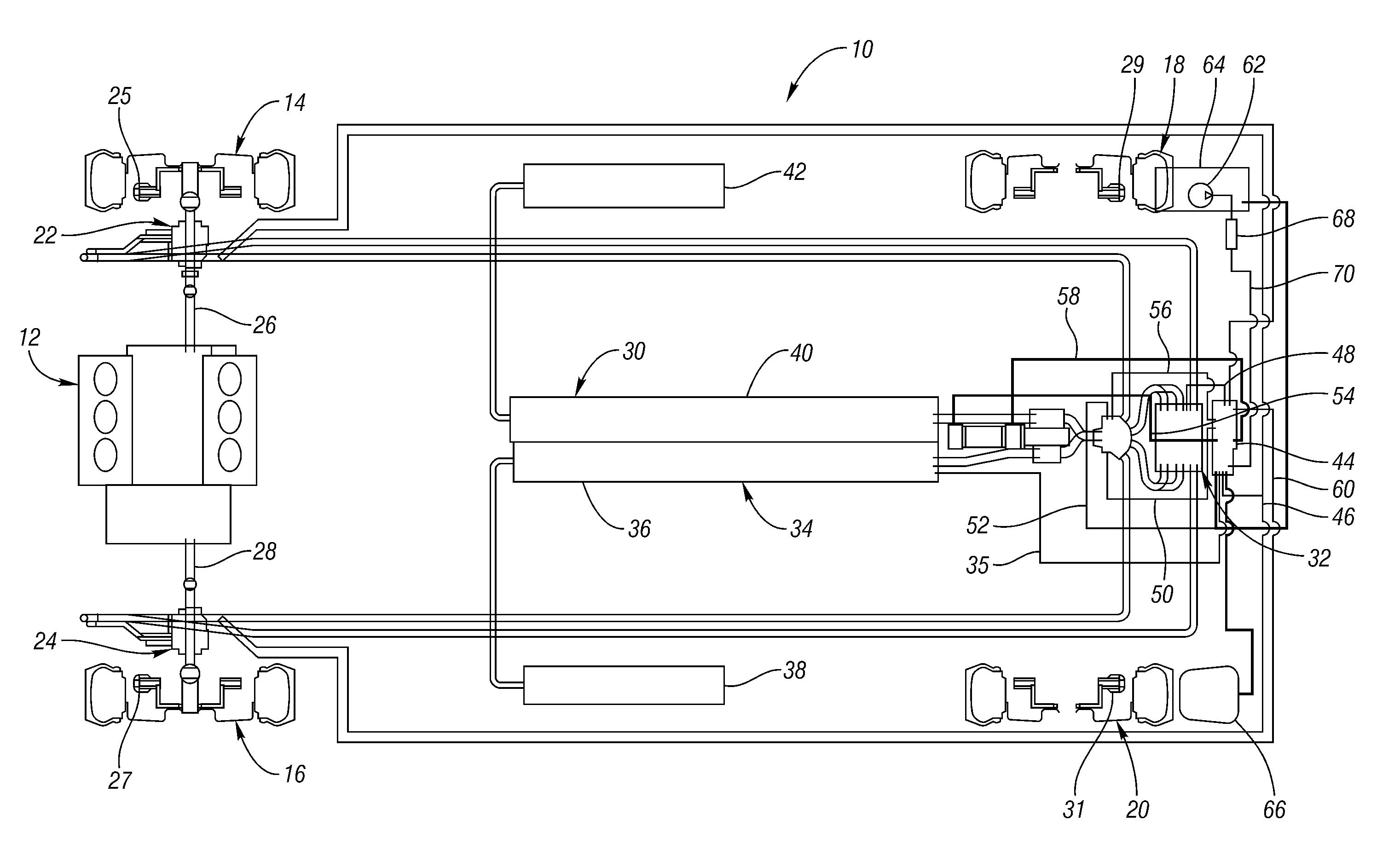
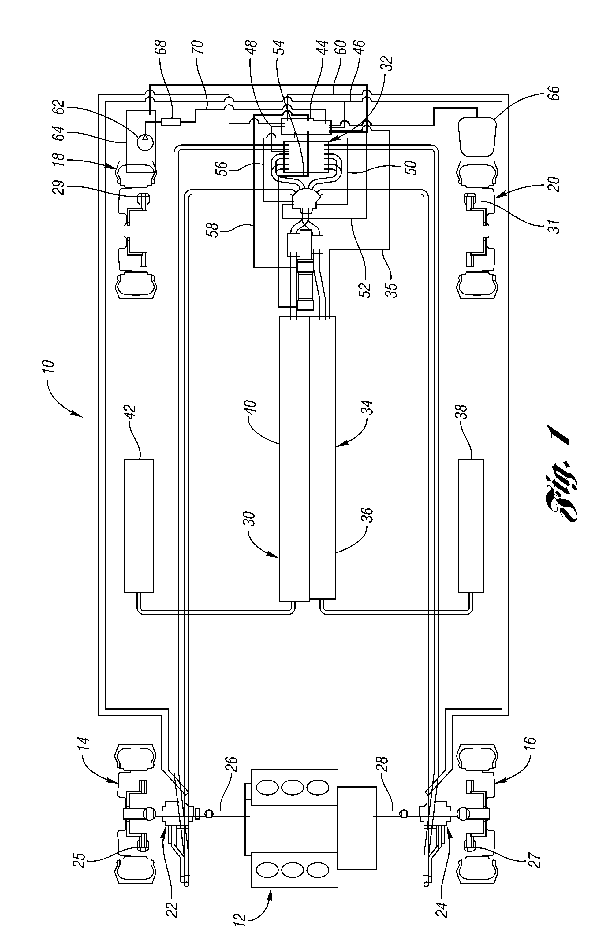
[0035]FIG. 1 shows a schematic representation of a hydraulic regenerative braking system 10 for a vehicle in accordance with the present invention. The vehicle, not shown in its entirety, includes an engine 12 and four wheels 14, 16, 18, 20. The regenerative braking system 10 includes two hydraulic machines, or pump-motors 22, 24. Each of the pump-motors 22, 24, is mounted on a respective driving shaft 26, 28 of the vehicle. Each pump-motor 22, 24 includes a torque arm 29—see FIG. 15B—which attaches to a ball-ended link to a secure mounting point on the vehicle chassis. As explained more fully below, each of the pump-motors 22, 24 is operable as a pump, driven by energy received from the respective vehicle wheels 14, 16 while the vehicle is braking.

[0036]The pump-motors 22, 24 pump fluid into a first, or high pressure accumulator 30, where the high pressure fluid is stored for later use. The pump-motors 22, 24 are also operable as motors, driven by fluid from the high pressure accu...


PUM


Abstract

A hydraulic regenerative braking system for a vehicle is provided. The system includes two hydraulic machines, each of which is disposed proximate a corresponding vehicle wheel. A transformer is in communication with each of the hydraulic machines, and with a pair of accumulators. Each of the hydraulic machines is operable as a pump, pumping fluid to at least one of the accumulators when the vehicle is braking. Each of the hydraulic machines is also operable as a motor, receiving pressurized fluid and transferring torque to the vehicle wheels. The transformer is operable to vary the pressure of the fluid received by the hydraulic machines.

Description

CROSS-REFERENCE TO RELATED APPLICATIONS[0001]This application claims the benefit of: U.S. provisional application Ser. Nos. 60 / 433,566 filed Dec. 16, 2002; 60 / 441,194 filed Jan. 21, 2003; 60 / 452,714 filed Mar. 10, 2003; 60 / 514,983 filed Oct. 29, 2003; and 60 / 523,337 filed Nov. 20, 2003.BACKGROUND OF THE INVENTION[0002]1. Field of the Invention[0003]The present invention relates to a hydraulic regenerative braking system for a vehicle.[0004]2. Background Art[0005]It is well known that hydraulic regenerative systems promise improved efficiency over electric regenerative systems incorporating a battery. Hydraulic regeneration involves using a pump, connected in the vehicle drive train, as a retarding device, and then storing the resulting high pressure fluid in an accumulator. On the subsequent vehicle acceleration, the high pressure fluid from the accumulator is routed to a hydraulic motor and the stored energy is recovered in the form of mechanical work which drives the vehicle forwa...

Claims


Application Information

Patent Timeline
Patent Type & Authority Patents(United States)
IPC IPC(8): B60T13/16B60K6/12B60TB60T1/10B60T8/64F15B21/14F16H61/40F16H61/4017
CPCB60K6/12B60T1/093B60T1/10B60T10/04B60T13/585B60W10/103B60W30/18127F15B21/14F16H61/4008F16H61/4017F16H61/4096Y02T10/6208F15B2211/88B60W20/00Y02T10/62B60W20/13B60W10/188
Inventor WALKER, FRANK H.
Owner WALKER FRANK H
Why Eureka
Try Eureka