
Method for manufacturing magnetostrictive torque sensor device, and electric power steering apparatus

a magnetostrictive torque and sensor device technology, applied in the direction of instruments, magnetic bodies, force/torque/work measurement apparatus, etc., can solve the problems of high linearity, low uniformity among individual sensors, and difficult to manufacture and widely distribute superior magnetostrictive torque sensors. achieve high rigidity, reduce non-uniform gain, and easily manufacture and widely distribute superior magnetostrictive torque sensors

Active Publication Date: 2009-08-04
HONDA MOTOR CO LTD
View PDF13 Cites 9 Cited by
  • Summary
  • Abstract
  • Description
  • Claims
  • Application Information

AI Technical Summary

Benefits of technology

[0015]In accordance with the invention, since the gain is adjusted by the gain adjuster of the detection circuit provided to the magnetostrictive torque sensor after the magnetostrictive torque sensor is installed in the gearbox, it is possible, even when there are variations in the applied torque or heating temperature and the amount of anisotropy or creep in the magnetostrictive films, to reduce nonuniformities in the gain of the magnetostrictive torque sensor output in a magnetostrictive torque sensor device that includes a magnetostrictive torque sensor in which the magnetostrictive films are heated while subjected to torque, the torque is canceled after cooling to create anisotropy, and detection coils detect changes in the magnetic characteristics of the magnetostrictive films. It is thereby possible to easily manufacture and widely distribute superior magnetostrictive torque sensor devices having high rigidity, good linearity, and minimal nonuniformities among individual sensors, and to reduce the management needed during the steps for providing anisotropy.
[0016]Since a gain-setting gain adjuster for electrically adjusting gain is provided, steps for sorting products according to characteristics are unnecessary, there is no need to prepare and store the sorted products in advance, and the assembly line can be simplified. It is thereby made possible to inexpensively manufacture and more widely distribute superior magnetostrictive torque sensor devices having high rigidity, good linearity, and minimal nonuniformities among individual sensors.
[0020]The gain is adjusted by means of the combined detection coils, detection circuit, and steering shaft having the magnetostrictive parts, whereby nonuniformities in the gain in the detection coils and detection circuit can be compensated and the precision of the coils and electric components can be simplified. It is thereby possible to inexpensively manufacture and more widely distribute superior magnetostrictive torque sensor devices having high rigidity, good linearity, and minimal nonuniformities among individual sensors.

Problems solved by technology

However, it is difficult in the manufacturing steps to manage all heating temperatures and torques applied to the steering shaft in the presence of anisotropy, and manufacturing has been complicated.
It has thereby been made difficult to widely provide torque sensors that are highly rigid, have a high degree of linearity, and have small uniformities among individual sensors.

Method used


Image

  • Method for manufacturing magnetostrictive torque sensor device, and electric power steering apparatus
  • Method for manufacturing magnetostrictive torque sensor device, and electric power steering apparatus
  • Method for manufacturing magnetostrictive torque sensor device, and electric power steering apparatus

Examples


first embodiment

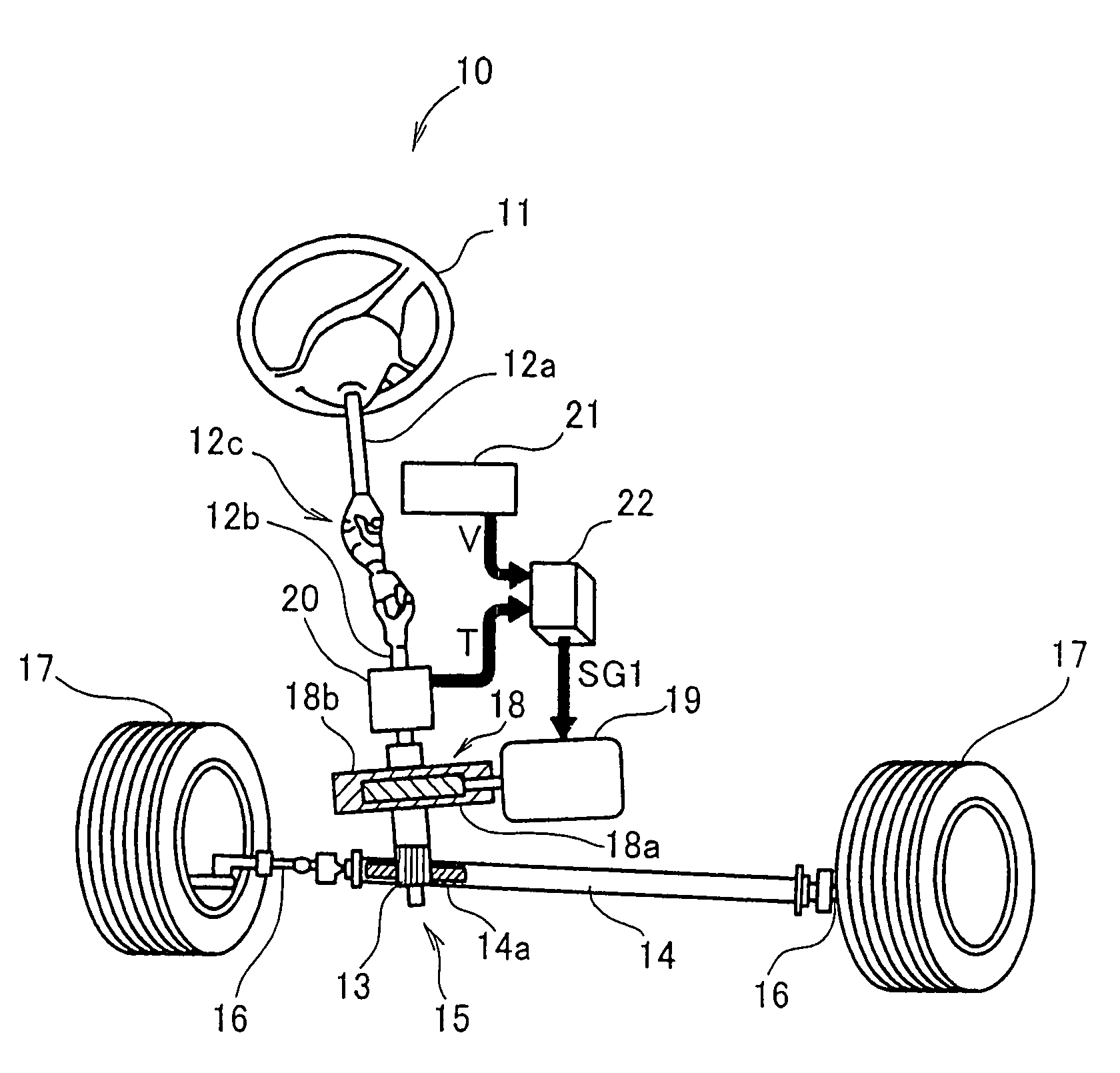
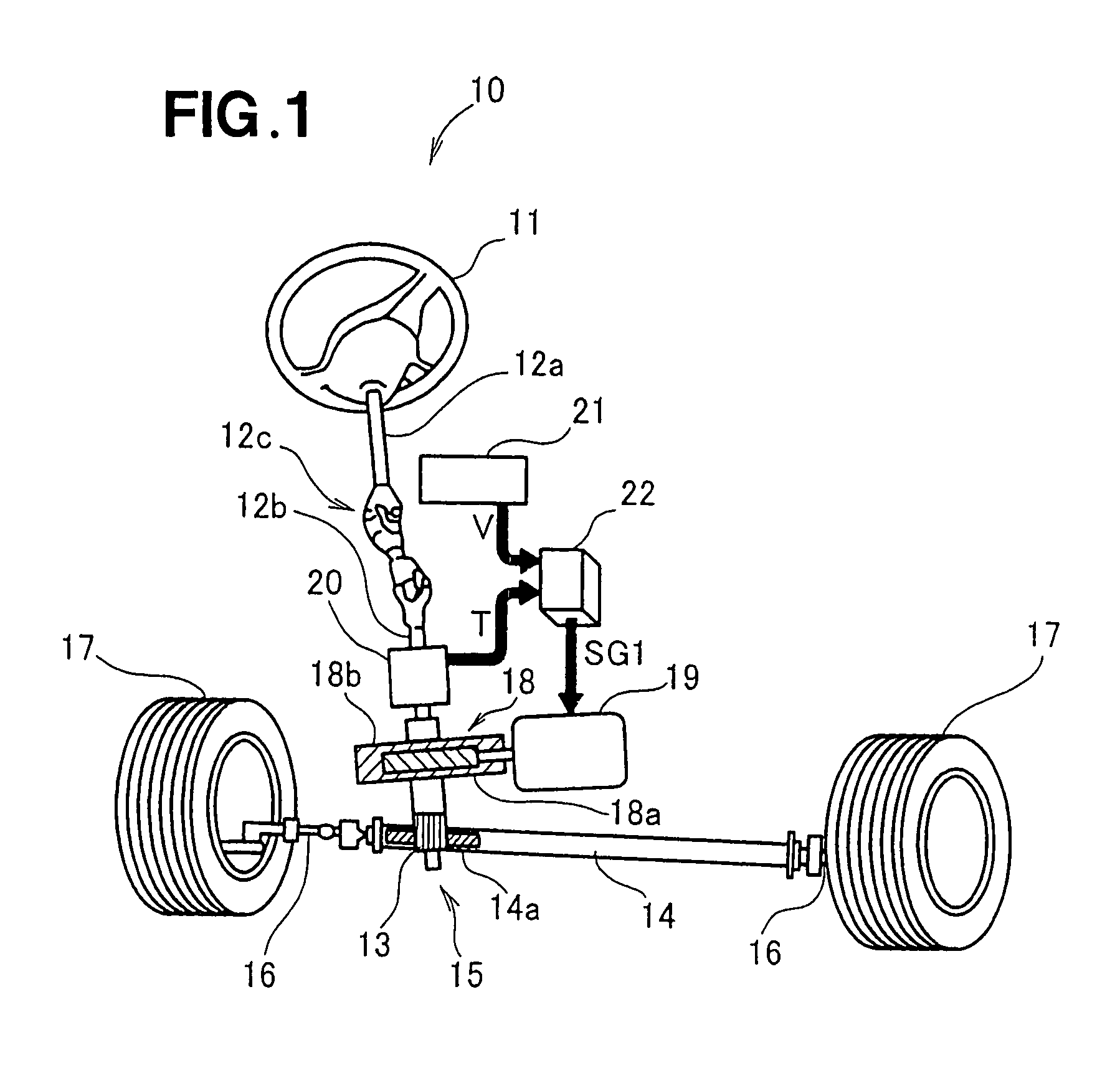
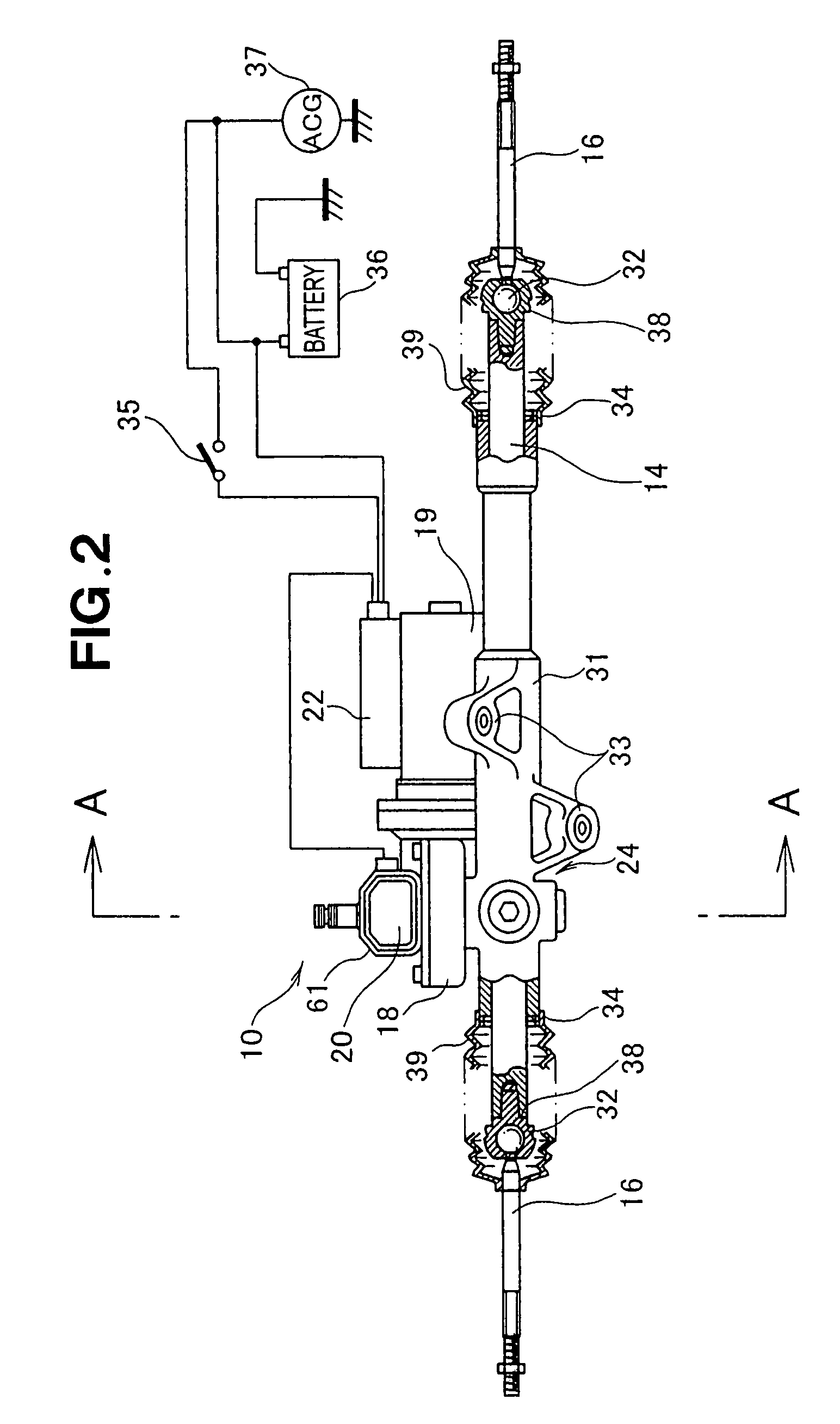
[0047]Reference is made initially to FIG. 1 showing the overall arrangement of an electric power steering apparatus according to the present invention. The electric power steering apparatus 10 is configured so that auxiliary steering torque is applied to a steering shaft 12a linked to a steering wheel 11. The steering shaft 12a is linked with a steering shaft 12b via a flexible drive coupling 12c, the top end of the steering shaft 12a is linked to the steering wheel 11, and a pinion 13 is attached to the bottom end of the steering shaft 12b. A rack shaft 14 is disposed on the pinion 13, providing a rack gear 14a that meshes with the pinion. A rack and pinion mechanism 15 is formed by the pinion 13 and the rack gear 14a. Tie-rods 16 are provided at both ends of the rack shaft 14, and front wheels 17 are attached to the outside ends of the tie-rods 16.

[0048]A motor 19 is provided to the steering shaft 12b via a power transmission mechanism 18. The power transmission mechanism 18 is fo...

second embodiment

[0091]FIG. 12 is a schematic view of the electric power steering apparatus according to the present invention.

[0092]An electric power steering apparatus 110 is composed of a steering system 120 that extends from a steering wheel 121 of a vehicle to steered wheels (e.g., front wheels) 131, 131 of the vehicle, and an auxiliary torque mechanism 140 for applying auxiliary torque to the steering system 120.

[0093]The steering system 120 has a configuration wherein a torque transmission shaft 124 is linked to the steering wheel 121 via a steering shaft 122 and flexible drive couplings 123, 123, a rack shaft 126 is linked to the torque transmission shaft 124 via a rack and pinion mechanism 125, and left and right steered wheels 131 are linked to the ends of the rack shaft 126 via ball joints 127, tie-rods 128, and knuckles 129.

[0094]The rack and pinion mechanism 125 is composed of a pinion 132 provided to the torque transmission shaft 124, and a rack 133 formed on the rack shaft 126.

[0095]T...


PUM

PropertyMeasurementUnit
thicknessaaaaaaaaaa
twisting torque Tqaaaaaaaaaa

Abstract

A method for manufacturing a magnetostrictive torque sensor device includes the steps of: providing a steering shaft or another such rotating shaft with two magnetostrictive parts endowed with magnetic anisotropy; disposing detection coils around the magnetostrictive parts to detect changes in magnetostrictive characteristics of the magnetostrictive parts; providing a detection circuit for bringing out detection signals from signals outputted from the detection coils; and adjusting a gain of a gain adjuster included in the detection circuit.

Description

FIELD OF THE INVENTION[0001]The present invention relates to a method for manufacturing a magnetostrictive torque sensor device, as well as to an electric power steering apparatus that includes a magnetostrictive torque sensor device made by such a manufacturing method.BACKGROUND OF THE INVENTION[0002]An electric power steering apparatus is a supporting apparatus that engages a motor to assist steering force when the driver operates the steering wheel while the automobile is moving. An electric power steering apparatus includes a steering torque sensor for sensing steering torque generated in a steering shaft by the handling operations of the driver. In an electric power steering apparatus, a steering torque signal outputted from the steering torque sensor and a vehicle speed signal outputted from a vehicle speed sensor are used to perform control by means of a motor drive controller and to use PWM to drive a supporting motor that outputs auxiliary steering force, thus reducing the ...

Claims


Application Information

Patent Timeline
Patent Type & Authority Patents(United States)
IPC IPC(8): B23P25/00
CPCG01L3/102G01L5/221G01L3/103Y10T29/4902Y10T29/49885Y10T29/49982
Inventor YONEDA, ATSUHIKOSHIMIZU, YASUOASAUMI, HISAOARIMURA, YUTAKA
Owner HONDA MOTOR CO LTD
Learn More