Thermally coupled liquid oxygen and liquid methane storage vessel

a technology of liquid oxygen and methane storage vessels, which is applied in the direction of container discharging methods, vessel construction details, transportation and packaging, etc., can solve the problems of limiting the amount of heat flow into the tank, reducing the life of cryogenic liquid, and reducing the structure and system. , to achieve the effect of reducing the structure and system

Inactive Publication Date: 2009-08-04
THE BOEING CO
View PDF12 Cites 11 Cited by
  • Summary
  • Abstract
  • Description
  • Claims
  • Application Information

AI Technical Summary

Problems solved by technology

A common problem in a liquid propellant rocket engine is cooling the combustion chamber and nozzle.
A fundamental physical problem in developing a propulsion system employing this bipropellant is storing the cryogenic LO2 and liquid methane (LCH4) with the least amount of boil-off due to heating and with the least amount of mass and power required.
Another problem is providing a means to drain single-phase liquid from the storage tank without an entrained gas phase.
Because both fluids are cryogenic, typical thermal environments on Earth and in space will cause the propellants to warm and tend to boil within the tanks.
Limiting the amount of heat flow into the tanks prolongs the lifetime of the cryogenic liquid because boil-off and the associated pressure increase is directly related to the amount of energy flow into the storage vessel.
However, such cryocoolers require relatively high electric power and generally operate continuously.
For spacecraft and other energy limited applications, large power consuming systems are undesirable.
Other more passive techniques that condition the fluids without the energy consumption of a cryocooler are known, but they typically operate with less cooling performance.
Another challenge in developing an oxygen and methane bipropellant system involves the draining of liquid tanks in low-gravity or highly dynamic acceleration environments to acquire a single phase liquid.
However, in low gravity, with no significant gravity field to pull it to one side of the tank, the specific liquid location within the tank is generally not known at all times because the liquid can easily move about the tank.
This results in a higher total mass of the tanks and the associated thermal conditioning hardware.

Method used


Image

  • Thermally coupled liquid oxygen and liquid methane storage vessel
  • Thermally coupled liquid oxygen and liquid methane storage vessel
  • Thermally coupled liquid oxygen and liquid methane storage vessel

Examples


Embodiment Construction
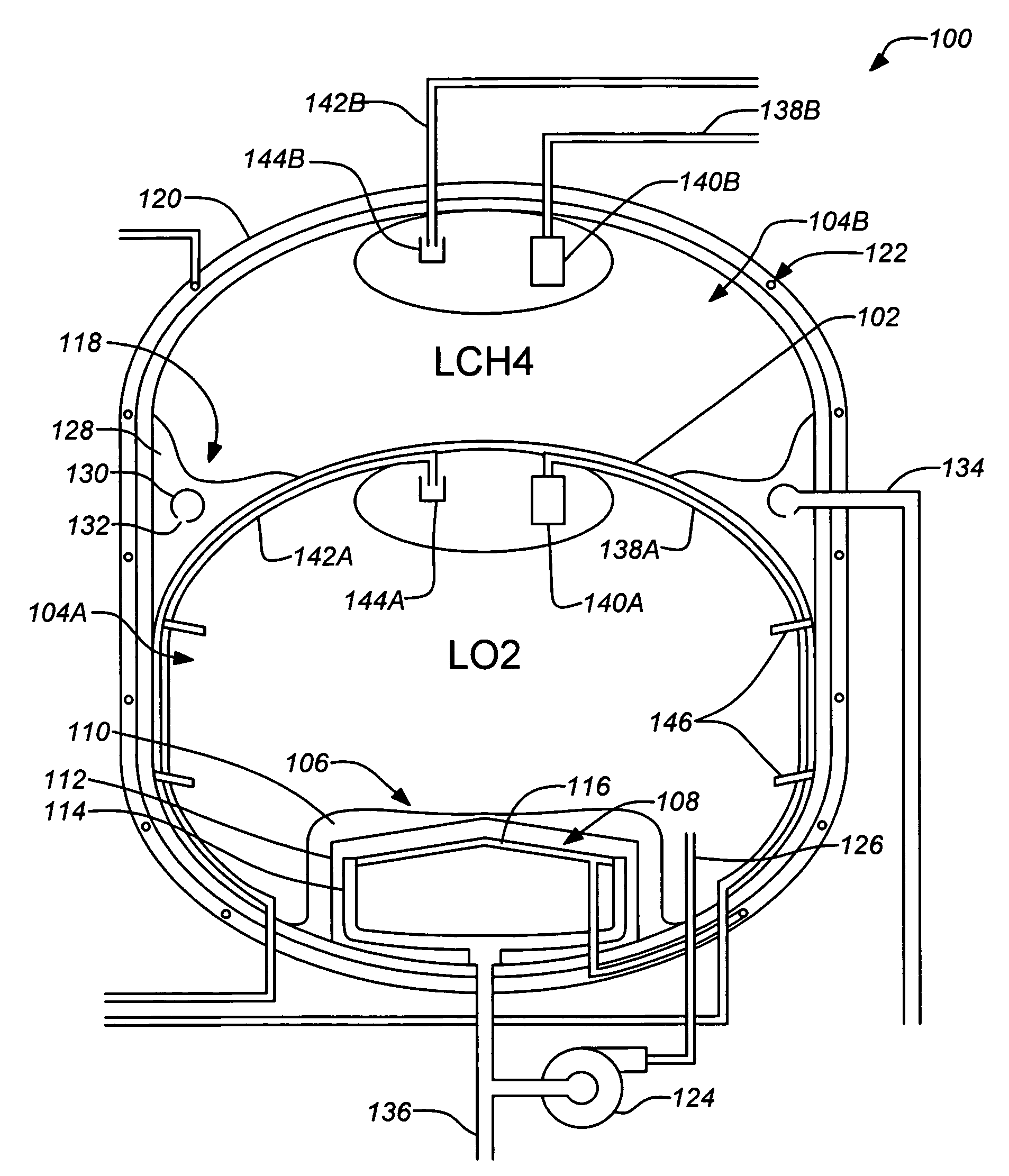
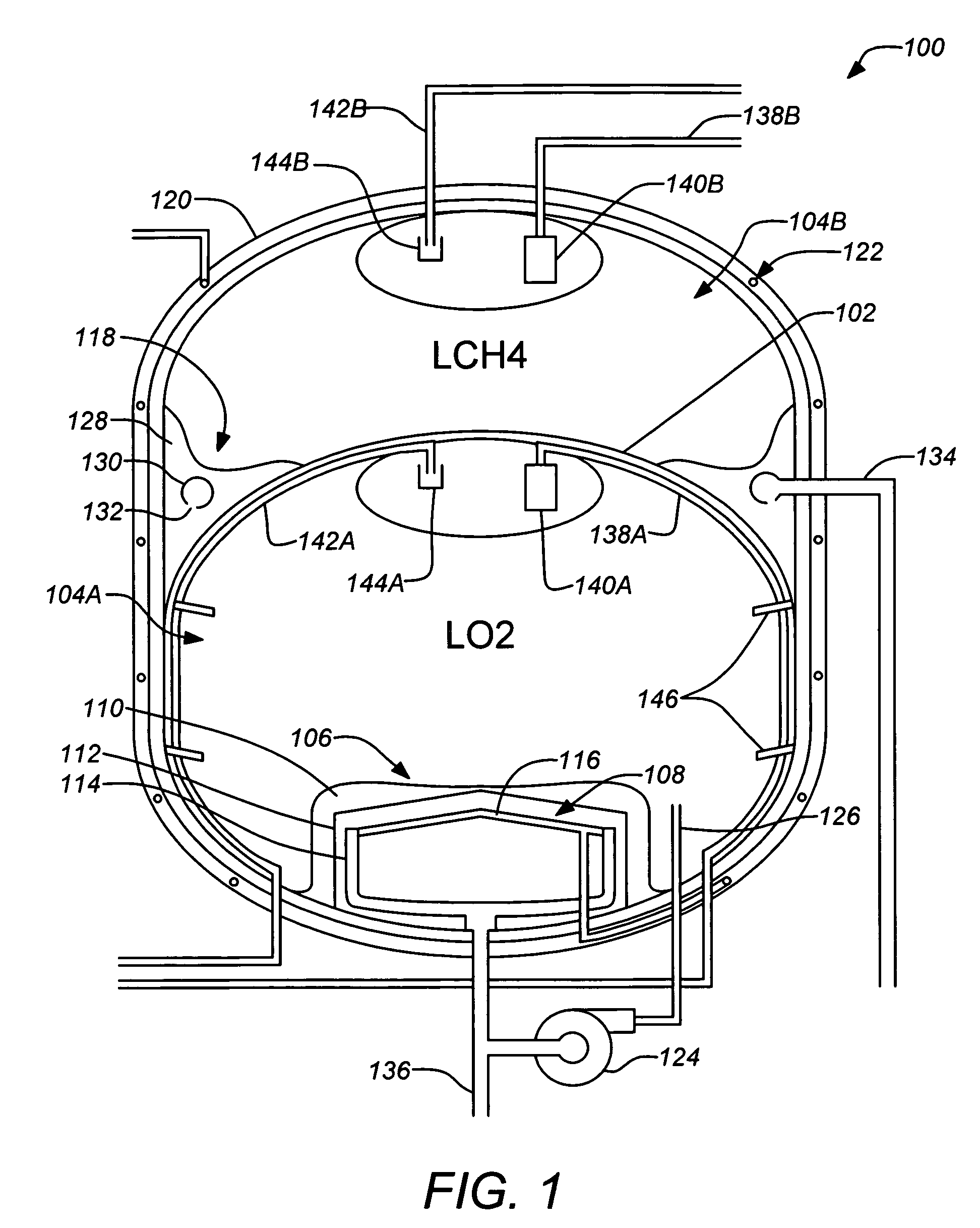
[0034]1. Overview

[0035]LO2 and LCH4 have relatively similar boiling temperatures on Earth; oxygen boils at 162° R while methane boils at 201° R. At a temperature near 164° R both fluids can exist in liquid phase if they are stored in tanks with the appropriate pressures. This allows the fluids to be thermally coupled, and thus stored at the same temperature which leads to several benefits. Although the invention described herein may be discussed with reference to the combination of LO2 and LCH4, those skilled in the art will understand that embodiments of the invention may be more broadly applied to other bipropellant combinations, provided a substantially similar functional operating temperature can be determined for the proposed bipropellant.

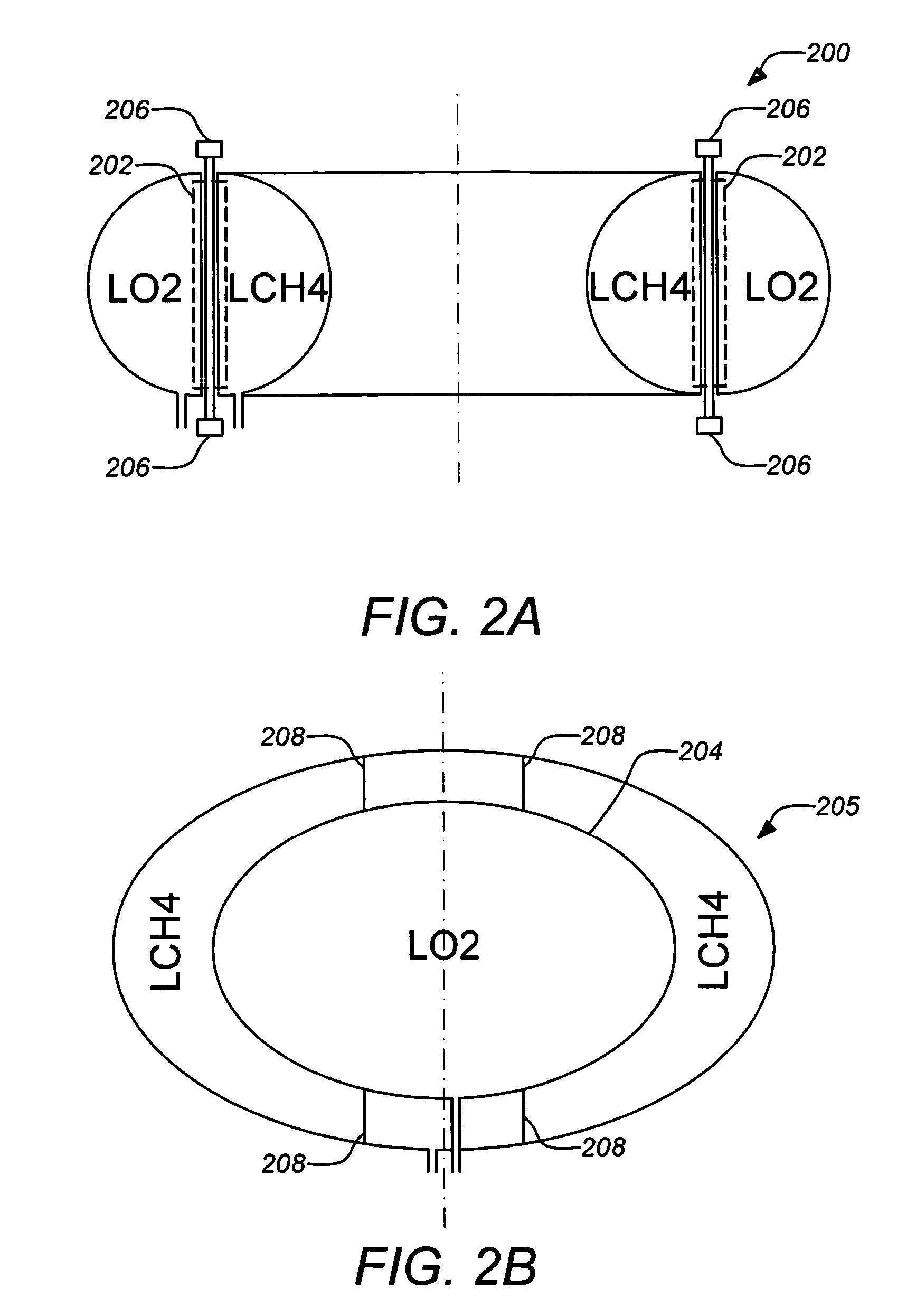
[0036]In various embodiments of the invention a cryogenic propellant storage tank system and method are disclosed that thermally couple LO2 and LCH4 tanks together by using either a single tank compartmentalized by a common tank wall or two se...


PUM


Abstract

A cryogenic propellant storage tank system and method are disclosed that thermally couple LO2 and LCH4 tanks together by using either a single tank compartmentalized by a common tank wall or two separate tanks that are coupled together with one or more thermal couplers having high thermal conductivity. Cryogenic cooling equipment may be located only in the LO2 tank while the LCH4 is cooled by the LO2 tank interface. Embodiments of the invention may employ both LO2 and LCH4 liquid acquisition devices (LADs) for low-gravity use. In further embodiments, only the LO2 LADs may be integrated with thermal cooling equipment.

Description

BACKGROUND OF THE INVENTION[0001]1. Field of the Invention[0002]This invention relates to fluid propellant propulsion systems and methods. Particularly, this invention relates to such propulsion systems and methods in space applications.[0003]2. Description of the Related Art[0004]A variety of liquid propellant systems have been proposed and developed to drive rockets and space vehicles. In most liquid propellant rocket engines, a fuel and an oxidizer, e.g. kerosene and liquid oxygen (LO2) are pumped into a combustion chamber where they burn to yield a high pressure and high velocity gas stream. The flow of the gas through a nozzle accelerates it further until it exits the engine. The exiting gas provides thrust in the opposite direction which is used to accelerate or maneuver the vehicle.[0005]In many space vehicles it is typical for the fuel and / or the oxidizer to be a cryogenic liquefied gas such as liquid hydrogen or LO2. A common problem in a liquid propellant rocket engine is ...

Claims


Application Information

Patent Timeline
Patent Type & Authority Patents(United States)
IPC IPC(8): F17C3/08F17C7/02
CPCF17C3/10F17C2270/0194F17C2201/0109F17C2201/0166F17C2203/0316F17C2203/0619F17C2203/0629F17C2205/0149F17C2221/011F17C2221/033F17C2223/0161F17C2223/033F17C2225/0161F17C2227/0339F17C2227/0365F17C2227/0376F17C2260/031F17C2201/0147
Inventor GRAYSON, GARY D.HAND, MICHAEL L.CADY, EDWIN C.
Owner THE BOEING CO
Why Eureka
Try Eureka