RF transmitter with variably biased RF power amplifier and method therefor

a power amplifier and rf transmitter technology, applied in the field of rf transmitters, can solve the problems of nonlinearity, nonlinearity, nonlinearity, nonlinearity, etc., and achieve the effect of increasing the strictness of the spectral mask, avoiding interference, and avoiding interferen

Inactive Publication Date: 2009-08-04
CRESTCOM INC
View PDF33 Cites 79 Cited by
  • Summary
  • Abstract
  • Description
  • Claims
  • Application Information

AI Technical Summary

Benefits of technology

[0017]It is an advantage of at least one embodiment of the present invention that an improved RF transmitter with a variably biased RF power amplifier and a corresponding method of operating the RF transmitter are provided.
[0019]Another advantage of at least one embodiment of the present invention is that a variably biased RF transmitter and method are provided which actively manage RF power amplifier linearity to achieve as much RF power amplifier efficiency as practical while meeting regulatory spectral mask constraints.
[0020]Another advantage of at least one embodiment of the present invention is that a variably biased RF transmitter and method are provided which actively manage RF power amplifier linearity to maintain out-of-band power below or equal to a predetermined level so that regulatory spectral mask constraints can be maintained.
[0021]Another advantage of at least one embodiment of the present invention is that a variably biased RF transmitter and method are provided which actively manage RF power amplifier linearity to maintain out-of-band power above or equal to a predetermined level so that as much RF power amplifier efficiency enhancement as possible can be achieved without violating regulatory spectral mask constraints.
[0022]Another advantage of at least one embodiment of the present invention is that a variably biased RF transmitter and method are provided which repeatedly make RF power amplifier linearity / efficiency transactions. When linearity may be degraded, linearity is “sold” in exchange for as much efficiency gain as possible, and when linearity needs to be improved, linearity is “bought” in exchange for as little efficiency loss as possible.

Problems solved by technology

While perfect linearity is a goal for any linear RF power amplifier, all linear RF power amplifiers invariably fail to meet it.
The degree to which the goal of perfect linearity is missed leads to unwanted intermodulation, nonlinearities, and spectral regrowth.
As transmitter technology has advanced, and as increasing demands have been placed on the scarce resource of the RF spectrum by the public, the spectral masks have become increasingly strict.
In conventional RF power amplifiers, the linearity parameter is counterbalanced against power-added efficiency.
Classes A, AB, and B are all considered suitable for linear amplification applications but are less efficient than classes C-F.
Each linear class is less efficient than all nonlinear classes.
As up-front costs for placing cellular base stations in service diminish, this on-going power cost is expected to become a larger portion of the overall lifecycle costs.
The use of multichannel signals also causes a peak-to-average power ratio (PAPR) of such signals to increase to extreme levels.
The EER technique is not used in high power and wide bandwidth applications because, rather than realizing efficiency enhancement, efficiency deterioration is the likely result along with reduced linearity.
Efficiency deterioration would result from attempting to generate a high power bias voltage that exhibits a bandwidth consistent with the amplitude content of a wide bandwidth signal.
But a linearity penalty still results, and the envelope-following technique is not used in high power and wide bandwidth applications because, rather than realizing efficiency enhancement, efficiency deterioration is the likely result.
But a linearity penalty still results, and nothing is provided to ensure that the linearity penalty does not result in the violation of a spectral mask.
These efficiency enhancements have had little success in connection with a high power, wide bandwidth application, such as in a cellular basestation.
On the other hand, while a cellular basestation's RF transmitter should be able to linearly amplify even the rare extreme peak amplitudes, the fact that these peaks occur so rarely affords an opportunity to benefit from efficiency enhancements because it is the average power level that influences power costs.

Method used


Image

  • RF transmitter with variably biased RF power amplifier and method therefor
  • RF transmitter with variably biased RF power amplifier and method therefor
  • RF transmitter with variably biased RF power amplifier and method therefor

Examples


Embodiment Construction

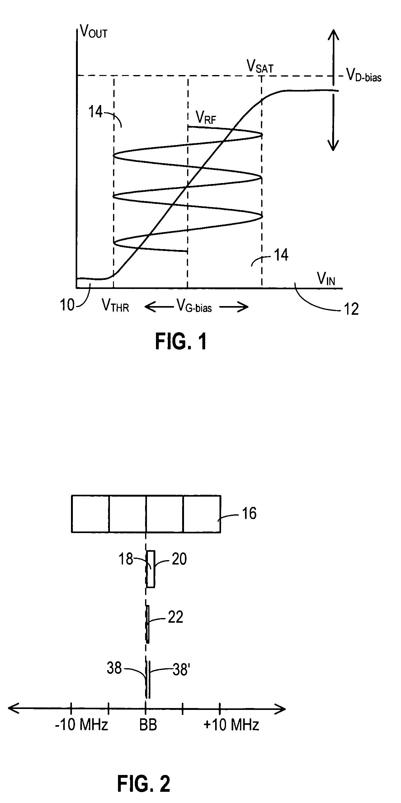
[0038]FIG. 1 shows a chart that graphically depicts transfer characteristics of a typical RF power amplifier. In the preferred embodiment of the present invention, an RF power amplifier, discussed in more detail below, is biased for substantially class A operation, and the chart of FIG. 1 depicts this class A operation. Three potential regions of operation are depicted. In a cutoff region 10, the input voltage is beneath a threshold (VTHR), and regardless of the precise input voltage, the output voltage exhibits the same low level. In a saturation region 12, the input voltage is greater than a predetermined level, but regardless of the precise input voltage, the output exhibits substantially the same high level. The size of cutoff region 10 is primarily determined by the semiconductor and other architectural characteristics of the RF power amplifier.

[0039]But the point at which the RF power amplifier transitions into saturation region 12 is determined in part by a bias voltage (VD-b...


PUM


Abstract

An RF transmitter (30) includes an RF power amplifier (32) for which the power input bias voltage (40) and signal input bias voltage (80) are controlled within feedback loops. A peak detector (44) generates a lowered-spectrum, peak-tracking signal (34) that follows the largest amplitude peaks of a wide bandwidth communication signal (16) but exhibits a lower bandwidth. This signal (34) is scaled in response to the operation of a drain bias tracking loop (146) then used to control a switching power supply (36) that generates the power input bias voltage. The tracking loop (146) is responsive to out-of-band power detected in a portion of the amplified RF communication signal (16″). A ratio of out-of-band power (128) to in-band power (126) is manipulated in the tracking loop (146) so that the power input bias voltage is modulated in a way that holds the out-of-band power at a desired predetermined level.

Description

TECHNICAL FIELD OF THE INVENTION[0001]The present invention relates generally to the field of radio-frequency (RF) transmitters. More particularly, the present invention relates to biasing RF power amplifiers used in RF transmitters and to the dynamic control of such biasing to achieve efficiency and linearity goals.BACKGROUND OF THE INVENTION[0002]An RF power amplifier provides the final stage of amplification for a communication signal that has been modulated and converted into an RF signal. Often that RF signal exhibits frequencies in a predetermined frequency band that is licensed by a regulatory agency for a particular use. The RF power amplifier boosts the power of this RF communication signal to a level sufficient so that the signal, when it propagates to an antenna, will be broadcast in such a manner that it will meet the communication goals of the RF transmitter.[0003]Many popular modern modulation techniques, such as CDMA, QAM, OFDM, and the like, require the RF power ampl...

Claims


Application Information

Patent Timeline
Patent Type & Authority Patents(United States)
IPC IPC(8): H01Q11/12H04B1/04
CPCH03C5/00H03F1/0205H03F1/0227H03F1/0261H03F1/3241H03F3/189H04B1/0475H03F3/24H04B2001/045H03F2200/105H03F2200/336H03F2200/435H03F2200/451H03F1/02
Inventor MCCALLISTER, RONALD DUANEBROMBAUGH, ERIC M.
Owner CRESTCOM INC
Why Eureka
Try Eureka