Pressure compensation structure for microelectromechanical systems

a technology of microelectromechanical systems and pressure compensation structures, which is applied in the field of microelectromechanical systems, can solve the problems of changing device performance and/or device failure, sealing actuator cavities in fluidic mems that are susceptible to pressure variations, and closed chambers of mems devices,

Inactive Publication Date: 2009-08-11
XEROX CORP
View PDF9 Cites 18 Cited by
  • Summary
  • Abstract
  • Description
  • Claims
  • Application Information

AI Technical Summary

Benefits of technology

[0006]In many current designs of fluidic MEMS having sealed cavity actuators, a 0.2-0.3 atm reduction in atmospheric pressure requires an additional 4-5 volts of driving voltage to operate the device. Some fluidic MEMS devices that incorporate sealed actuator cavities trap gas as the result of contamination, chemical reaction, or outgassing of structural, residual sacrificial, or packaging materials. For example, some embodiments of fluidic MEMS having sealed actuator cavities are fabricated with a process that requires an actuator to be sealed by organic materials such as SU8 polymer. The internal pressure of the device in the vicinity of the actuator may be altered by the out-gassing of the sealing materials. In one particular application, ambient pressure changes or internal pressure changes may cause an inkjet print head that incorporates a fluidic MEMS having a sealed actuator cavity to experience degradation in the jetting speed, drop volume, directionality, or overall print quality produced by the print head. For all these reasons, reduced sensitivity of actuators in fluidic MEMS devices to pressure fluctuations is desirable.
[0009]In one embodiment of a fluidic MEMS device that compensates for changing pressure conditions, the pressure compensating chamber is covered with a flexible covering that is more responsive to pressure fluctuations than the actuator membrane. The flexing of the covering enables the fluid in the pressure compensating chamber to absorb the pressure differential before the actuator membrane responds. Thus, the effect of the changing pressure on the actuator cavity is negligible. The covering over the pressure compensating chamber may be rendered more flexible than the actuator membrane by constructing the flexible covering with a width and length relative to the width and length of the actuator membrane in a manner described in more detail below.

Problems solved by technology

A MEMS device with a closed chamber, a sealed membrane, or other fluid delivery system may be susceptible to differential pressure.
Differential pressure may cause undesirable membrane deflection, including bulging or collapsing membranes, trapped bubbles or fluids in the cavities behind the membranes or cracking or bursting resulting in a change of device performance and / or device failure.
A sealed actuator cavity in a fluidic MEMS can be susceptible to the pressure variations.
Thus when a device embodying a fluidic MEMS is transported from one location, such as a manufacturing location, to another location at a substantially different altitude, such as a user's location, the sealed cavity of the fluidic MEMS is subjected to pressure changes that may result in the fluidic MEMS operating outside of its design parameters.
In one particular application, ambient pressure changes or internal pressure changes may cause an inkjet print head that incorporates a fluidic MEMS having a sealed actuator cavity to experience degradation in the jetting speed, drop volume, directionality, or overall print quality produced by the print head.
This approach to addressing pressure differential problems may cause stiction concerns because humidity in the air may result in condensation that leads to capillary forces that cause stiction.
This embodiment, however, is not responsive to ambient pressure changes because the plate and rigid walls do not respond to ambient pressure changes as the flexible covering does in the embodiment described earlier.

Method used


Image

  • Pressure compensation structure for microelectromechanical systems
  • Pressure compensation structure for microelectromechanical systems
  • Pressure compensation structure for microelectromechanical systems

Examples


Embodiment Construction

[0021]For the purposes of promoting an understanding of the principles of the disclosure, reference is now made to the embodiments illustrated in the drawings and described in the following written specification. No limitation to the scope of the disclosure is intended by these particular depictions and their descriptions.

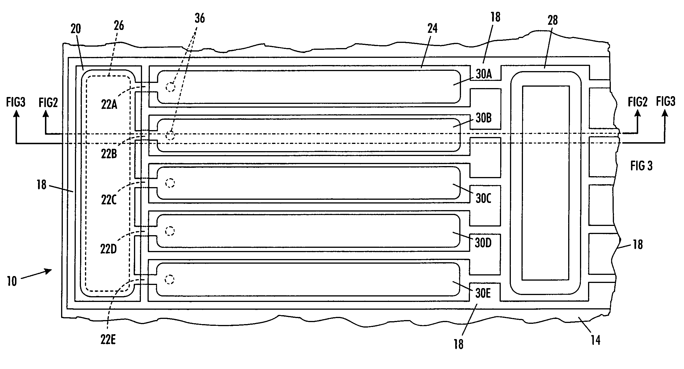
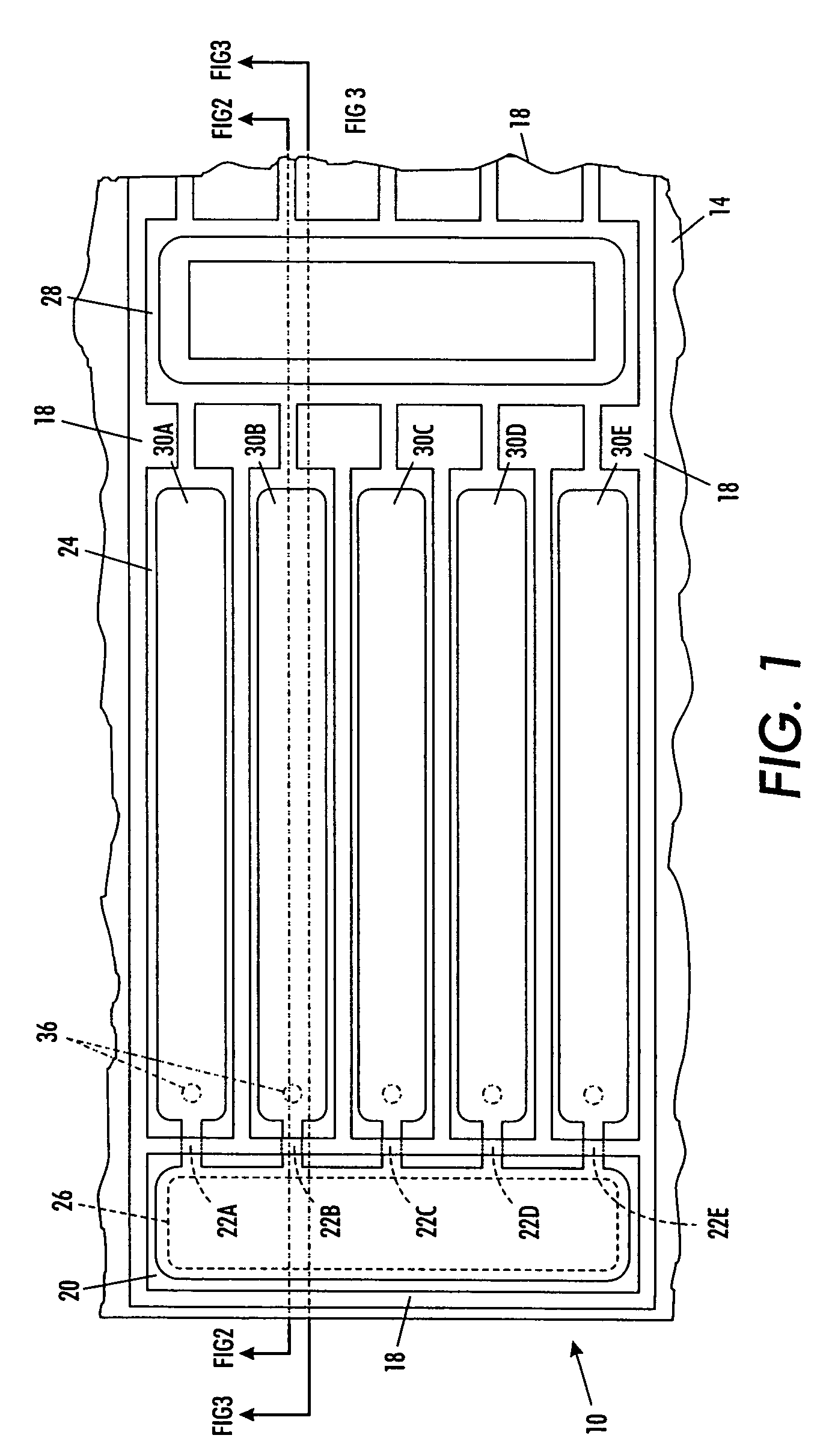
[0022]A top view of one embodiment of a fluidic MEMS device 10 is shown in FIG. 1. The device 10 includes a substrate 14. There are three main MEMS structure regions on top of substrate 14. There regions are a pressure compensating region 20, an actuator area 24, and an inlet area 28. The substrate may be made from a suitable substrate material for a particular application, such as silicon, and the tall sidewalls 18 that are constructed on top of the silicon substrate may be made of a suitable material, such as nickel. Within actuator area 24 are a plurality of rigid walls that extend across the width of the area to divide the actuator area into a plurality of actu...


PUM


Abstract

A fluidic micro-electromechanical device includes a pressure compensating subsystem that enables the device to operate consistently in changing environmental pressure conditions. Such a fluidic micro-electromechanical device includes an actuator having an actuator cavity underneath an actuator membrane, the actuator membrane moving in response to a driving signal applied to an actuator electrode, and a pressure compensating chamber coupled to the actuator cavity.

Description

BACKGROUND AND SUMMARY[0001]The systems described herein relate to micro-electromechanical systems (“MEMS”) and, more particularly, to MEMS having structures containing fluids.[0002]Micro-electromechanical systems are mechanical systems that are micromachined in silicon and may be optionally integrated with control electronic circuits. MEMS are generally categorized as either microsensor or microactuator systems, depending on the application. MEMS incorporate electrostatic, electromagnetic, thermoelastic, piezoelectric, or piezoresistive effects in the operations of the systems.[0003]Fluidic MEMS often include a closed chamber, sealed membrane, or other fluid passageway. A MEMS device with a closed chamber, a sealed membrane, or other fluid delivery system may be susceptible to differential pressure. This pressure variation can occur during various stages of a device's lifetime from processing, storage, or shipping of the device for operation at different locations. For example, the...

Claims


Application Information

Patent Timeline
Patent Type & Authority Patents(United States)
IPC IPC(8): B41J2/045
CPCB41J2/055B41J2/14201B81B3/0059B41J2/14314B81B2201/058
Inventor JIA, NANCY Y.NYSTROM, PETER J.DOMOTO, GERALD A.GULVIN, PETER M.
Owner XEROX CORP
Why Eureka
Try Eureka