
PCD drill for composite materials

a composite material and drill bit technology, applied in the direction of twist drills, manufacturing tools, wood boring tools, etc., can solve the problems of preventing the use of automated systems capable of drilling and fastening components, affecting the proper fit of fasteners, and difficult drilling of cfrp components, etc., to achieve low production rate, high hole quality, and minimal delamination

Active Publication Date: 2009-08-18
PRECORP INC
View PDF43 Cites 57 Cited by
  • Summary
  • Abstract
  • Description
  • Claims
  • Application Information

AI Technical Summary

Benefits of technology

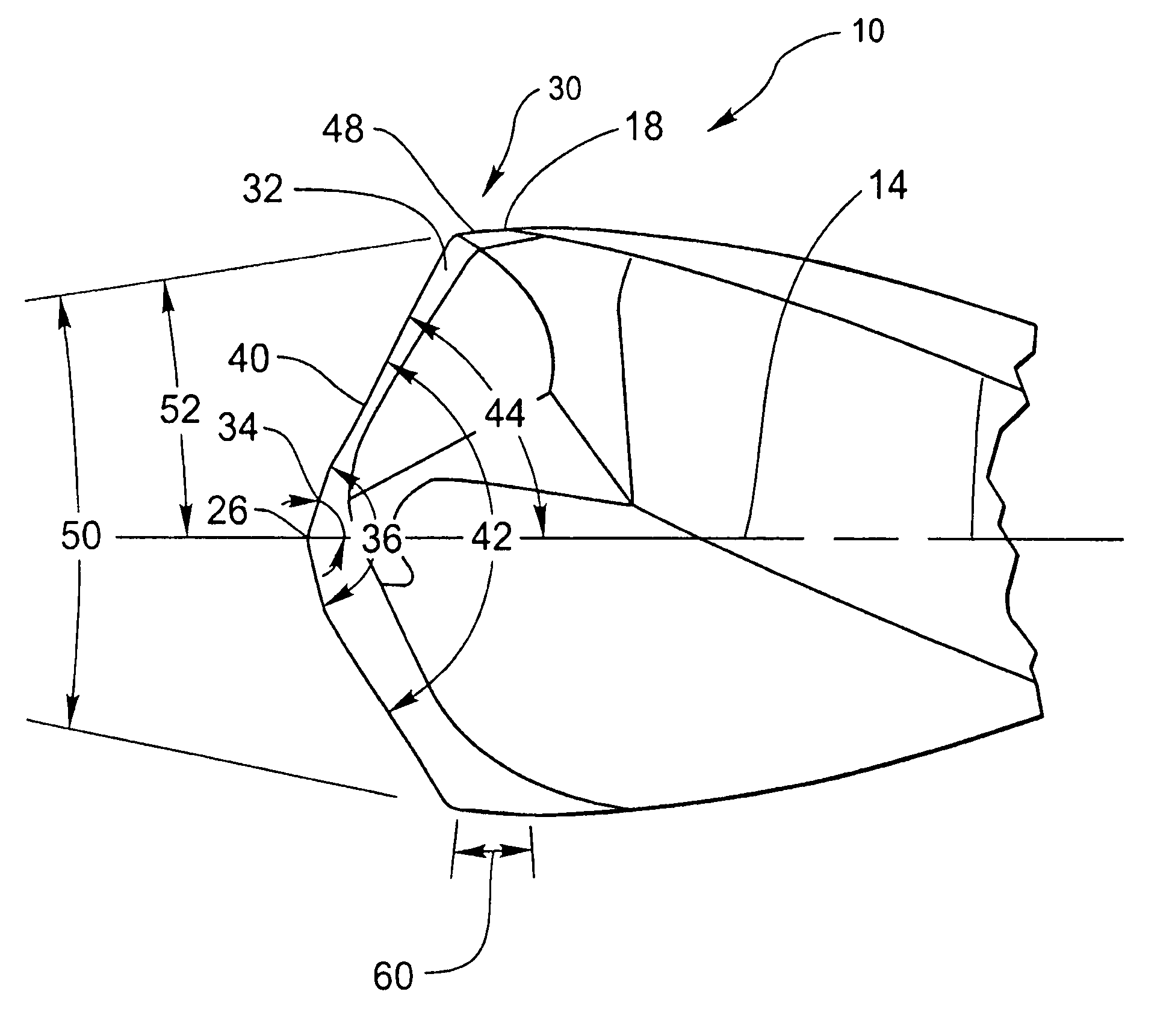
[0011]The apparatus and method of the present invention have been developed in response to the present state of the art, and in particular, in response to the problems and needs in the art that have not yet been fully solved by currently available drills and related hardware and methods used in drilling advanced composite materials such as CFRP. The drill configurations of the invention provide unique drills and combination drills and countersinks that can produce close tolerance precision holes in advanced composite laminates at high production rates with minimal delamination and high hole quality.
[0012]In some embodiments, the drills and combination drills with countersinks of the invention may include a polycrystalline diamond “PCD” cutting face to provide for longer tool life and extend the range of materials for which the drills and combination drills are suitable. Similarly, the unique drills or combination drills with countersinks of the invention may be constructed such that they may reconditioned, in some cases multiple times, thus allowing for more economical drilling costs.
[0013]In one embodiment of the invention, the drill comprises a helically-fluted cylindrical body with a symmetrically multi-faceted drill point. On the drill point, one set of symmetrical cutting edges located at the outer diameter of the drill provides a high shearing action at the peripheral edge of the drill to remove uncut fibers during drilling and during the exit of the drill from the hole. This embodiment may further include a set of more centrally-placed symmetrical cutting edges which form an obtuse angle that then intersects with the before-mentioned acute faceted cutting edges. In some embodiments, the very center of the drill may be formed into a very narrow point by the addition of two additional symmetrical cutting edges which may greatly reduce the cutting forces of the drill during use.
[0014]This unique drill point of the invention may also be produced with a second major diameter used to counterbore or countersink the hole produced by the drill point. In some situations, drilling and countersinking the hole in one operation may be preferred in order to achieve accurate placement of the countersink or counterbore and to save time in the manufacturing process.

Problems solved by technology

Drilling of CFRP components is difficult, however, as a result of the highly abrasive nature of the material and its tendency to delaminate and fray when processed by conventional drills.
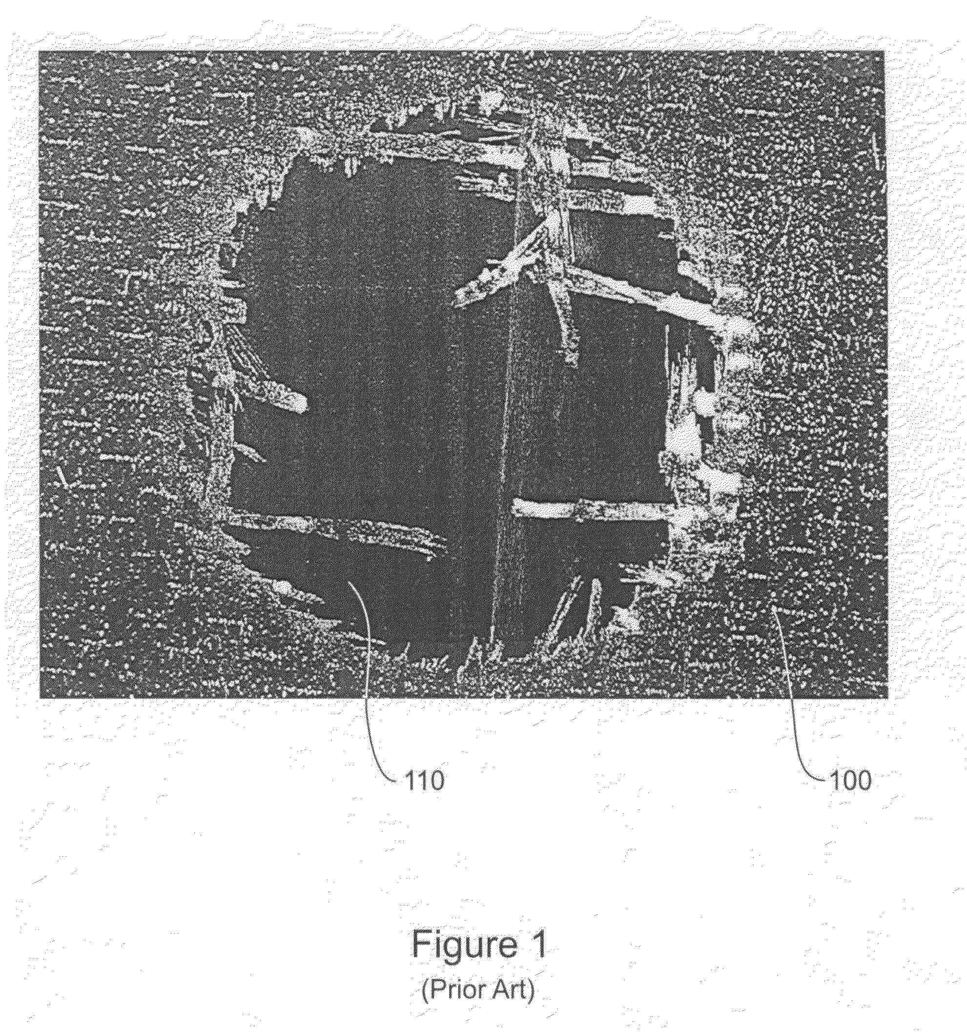
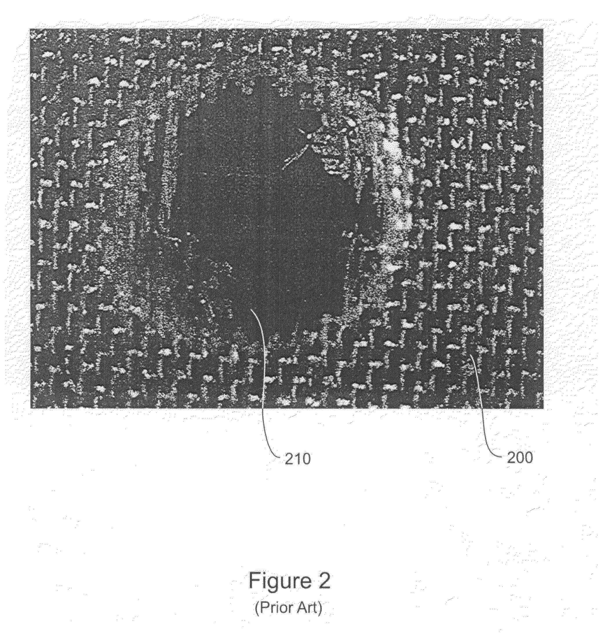
One of the more serious problems experienced in drilling CFRP occurs when the exit of the drill from the hole produced leaves uncut fibers exposed in the hole.
Such fibers can then interfere with the proper fit of the fastener used to join the materials.
Forced inclusion of such a manual step prevents the use of automated systems capable of drilling and fastening components in a single operation.
This may greatly increase the manufacturing time and costs of items constructed with CFRP components.
In addition to the above, it is understood in the art that the drilling speeds and feed rates used with conventional drills in conventional materials are unsuitable in CFRP-based components.
In such systems, keeping the cutting edge cool is made difficult by the low thermal conductivity of the resin matrix of the CFRP.
While chips produced in the machining of aluminum carry away heat, cuttings produced by machining advanced composite materials such as CFRPs carry away very little of the heat generated by the machining process.
As a result, heat buildup in the cutting zone is common.
Such an accumulation of heat may cause the resin to oxidize and / or degrade, thus increasing risk of delamination and decreasing the quality and shape of the hole produced in the component and increasing the likelihood of uncut fibers.
In addition to the above, the widely different material properties of the fiber and resin matrix encapsulating the fibers in CFRP components also render machining of the product difficult.
Specifically, even slight dulling of currently-used tool cutting edges can cause delamination of CFRPs and displacement of fibers from their positions in the resin matrix of the CFRP.
Even modest cutting forces can cause delamination or leave residual stresses.
This reduction in drilling speed further adds to the costs of machining composite laminate components.
Such an approach requires highly specialized machinery, however.
This machinery cannot be used in many of areas of aircraft assembly and takes considerably greater time to form each hole.
As with the prior art drilling and post-processing methods discussed above, such orbital milling approaches may greatly inflate the cost and time of machining.

Method used


Image

  • PCD drill for composite materials
  • PCD drill for composite materials
  • PCD drill for composite materials

Examples


Embodiment Construction

[0037]The presently preferred embodiments of the present invention will be best understood by reference to the drawings, wherein like parts are designated by like numerals throughout. It will be readily understood that the components of the present invention, as generally described and illustrated in the figures herein, could be arranged and designed in a wide variety of different configurations. Thus, the following more detailed description of the embodiments of the twist drills of the present invention, as represented in FIGS. 1 through 9, is not intended to limit the scope of the invention, as claimed, but is merely representative of presently preferred embodiments of the invention.

[0038]The present invention provides an improved helical flute twist drill for drilling advanced composite laminates such as CFRP and fiberglass laminates. Some embodiments of the invention utilize a polycrystalline diamond (or “PCD”) cutting edge with a tough tungsten carbide body. Such configurations...


PUM

PropertyMeasurementUnit
Lengthaaaaaaaaaa
Angleaaaaaaaaaa
Angleaaaaaaaaaa

Abstract

A PCD drill for producing close tolerance holes in multi layer laminates, such as carbon fiber reinforced composites, with minimum fraying of the fibers on both entrance and exit from the hole is provided. The drills provided include a symmetrical cutting point with a self-centering split point and a high shear second cutting lip positioned at the outer diameter of the drill. The drills of the invention may allow for increased cutting speeds and feeds when used with such advanced composite materials, thus increasing tool productivity and providing increased performance.

Description

BACKGROUND OF THE INVENTION[0001]Multi-layer laminates such as carbon fiber-reinforced composites (CFRP) and fiberglass composites (FRP) have become widely used in recent years in a large number of applications. These laminate materials most often consist of woven layers of strong fibers that are coated with resins and processed or cured to form a solid structure. Depending on the choice of the fibers and the resin systems used, these materials can be formulated and molded to produce components with excellent mechanical properties and unique geometries that would be difficult or impossible to obtain using other materials.[0002]The properties of high strength CFRP materials may be widely varied by manipulating the characteristics of the matrix formulation, as well as the fiber type, content, orientation, build-up, and the methods used to shape these materials into a finished structure. This variability and the general strength of CFRP materials make them useful in a wide variety of a...

Claims


Application Information

Patent Timeline
IPC IPC(8): B23B51/02
CPCB23B51/02B23B51/108B23B2226/275B23B2226/315Y10T408/906B23B2251/14B23B2251/18Y10T408/81Y10T408/9097B23B2251/043
Inventor GARRICK, RICHARD M.BUNTING, JOHN A.
Owner PRECORP INC
Learn More