Method for synthesis of colloidal nanoparticles

a colloidal nanoparticle and synthesis method technology, applied in the field of chemical synthesis of colloidal nanoparticles, can solve the problems of high temperature method imposing a limiting factor for industrial scalability and rapid discovery of nanomaterials, time and cost required for each individual reaction preparation, and low product yield for device applications, etc., to achieve enhanced nanoparticle formation rate and high crystallinity of nanoparticles

Inactive Publication Date: 2009-08-18
RGT UNIV OF CALIFORNIA
View PDF6 Cites 24 Cited by
  • Summary
  • Abstract
  • Description
  • Claims
  • Application Information

AI Technical Summary

Benefits of technology

[0012]To overcome the limitation in the prior art described above, and to overcome other limitations that will become apparent upon reading and understanding the present specification, the present invention describes methods of chemical synthesis of nanoparticles, such as quantum dots, comprising a high temperature ramp process, warranting large-scale, safe, convenient, reproducible, and energy-efficient production.
[0019](5) high crystallinity of the nanoparticles that is often achieved by employing the results of the present invention.

Problems solved by technology

One of the major hurdles for industrialization of these materials has been the development of a reproducible, high quantity synthetic methodology that is adaptable to high throughput automation for preparation of quantities of >100's of grams of single size (<5% RMS) crystalline quantum dots of various composition to be isolated.
[14-19] The high temperature method imposes a limiting factor for industrial scalability and rapid nanomaterial discovery for several reasons: (1) random batch-to-batch irregularities such as temperature ramping rates and thermal instability; (2) time and cost required for preparation for each individual reaction; and (3) low product yield for device applications.
While recent advances in the field have developed better reactants, including inorganic single source precursors, metal salts, and oxides; better passivants, such as amines and non-coordinating solvents; and better reaction technologies, such as thermal flow reactors; the reactions are still limited by reproducibility.
Coupled to this problem is the lack of control over reaction times, which require continuous monitoring.
In the case of III-V compound semiconductors, the synthetic pathways have rates of growth on the order of days, while in the case of II-VI's, size control is very difficult and depends on the ability to rapidly cool the reaction.

Method used


Image

  • Method for synthesis of colloidal nanoparticles
  • Method for synthesis of colloidal nanoparticles
  • Method for synthesis of colloidal nanoparticles

Examples


example 1

Preparation of CdSe from a Single Source Precursor Li4[Cd10Se4(SPh)16]

[0095]It has been shown by Cumberland et al. in [7] that a novel single source precursor based upon Li4[Cd10Se4(SPh)16] in the presence of mild coordinating alkyl amine solvent can yield CdSe quantum dots in the size range of 2-9 nm with a reaction time of 720 minutes on average. Using this single source precursor in the presence of hexadecylamine (HDA) microwave irradiation yields nanoparticles in a fraction of the time.

[0096]50 g of HDA was degassed under vacuum at 110° C. 80 mg of Li4[Cd10Se4(SPh)16] was placed in the reaction vessel and sealed with a high pressure crimp cap followed by the addition of 4 ml of molten, degassed HDA (at approximately 70° C.). The reaction vessel was placed in the chamber of the microwave reactor and irradiated with 300 Watts of power until it reached 230° C., at which time the power was decreased to 230 Watts. This power and temperature was held constant for 60 minutes. At 60 min...

example 2

Preparation of CdSe from a Single Source Precursor Li4[Cd10Se4(SPh)16] and 1-hexyl-3-methylimidazolium Chloride

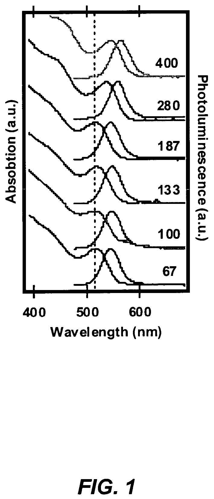
[0099]The CdSe was prepared using the single source precursor Li4[Cd10Se4(SPh)16]2. A stock solution of the precursor cluster was prepared by adding 635 mg of Li4[Cd10Se4(SPh)16] and 0.0448 g of 1-hexyl-3-methylimidazolium chloride to 45 g of degassed 1-aminohexadecane at 90° C. The solution was degassed under Ar, and 5 ml aliquots were injected into the microwave reaction vials prior to the reaction. A series of reaction were performed in which the applied power was increased from 160 to 400 W keeping the reaction time at 3 minutes and the temperature fixed at 210° C. by active cooling.

[0100]An important characteristic of dielectric heating is that microscopic instantaneous temperatures can be reached with small amounts of ionic liquid. It is clear from FIG. 1 that the onset of the first exciton redshifts with increasing power. That is, the CdSe nanoparticles in the microw...

example 3

Preparation of CdSe from CdNO3 and TOP: Se.

[0101]Stock solutions of Cd and Se were prepared separately. The cation solution was prepared by dissolving 435 mg of cadmium nitrate tetrahydrate in 9.6 ml of trioctylphosphine (TOP). This solution was heated to 100° C. under vacuum for 30 minutes. The reaction mixture was purged with Ar three times and then cooled to room temperature for later use. The anion solution was prepared by mixing 182 mg of 200 mesh Se powder in 2.8 ml TOP The coordinating solvent, trioctyphosphine oxide (TOPO), was degassed under vacuum at 110° C. three times and back filled with Ar over a two hour period. The Cd (0.5 ml) and Se (0.6 ml) were mixed in a teflon sealed reaction vial, and diluted with 3.9 ml molten TOPO (approximately 65° C.) to make a 5 ml solution. The reaction vessel was placed in the chamber of the microwave reactor at room temperature. 300 Watts were applied for several seconds, at which time the temperature spiked from 40° C. to 230° C. in 15...


PUM

PropertyMeasurementUnit
room temperatureaaaaaaaaaa
frequencyaaaaaaaaaa
cooling rateaaaaaaaaaa

Abstract

A method for synthesis of high quality colloidal nanoparticles using comprises a high heating rate process. Irradiation of single mode, high power, microwave is a particularly well suited technique to realize high quality semiconductor nanoparticles. The use of microwave radiation effectively automates the synthesis, and more importantly, permits the use of a continuous flow microwave reactor for commercial preparation of the high quality colloidal nanoparticles.

Description

CROSS REFERENCE TO RELATED APPLICATION[0001]This application is a continuation-in-part and claims the benefit under 35 U.S.C. Section 120 of the following co-pending and commonly-assigned patent application:[0002]Ser. No. 10 / 945,053, filed on Sep. 20, 2004, by Geoffrey F. Strouse, Jeffrey A. Gerbec, and Donny Magana, entitled METHOD FOR SYNTHESIS OF COLLOIDAL NANOPARTICLES, attorneys' docket number 30794.111-US-U1,[0003]which application is incorporated by reference herein.BACKGROUND OF THE INVENTION[0004]1. Field of the Invention[0005]The invention is related to chemical synthesis of nanoparticles, and more particularly, to the large-scale, safe, convenient, reproducible, energy-conserving synthesis of highly-dispersive inorganic nanoparticles with narrow size distribution.[0006]2. Description of the Related Art[0007](Note: This application references a number of different publications as indicated throughout the specification by one or more reference numbers within brackets, e.g.,...

Claims


Application Information

Patent Timeline
Patent Type & Authority Patents(United States)
IPC IPC(8): B29B9/00B29C67/00
CPCB01J13/00H05B6/806B82Y10/00B82Y20/00B82Y30/00C01G3/00C01G3/02C01G5/00C01G9/00C01G9/08C01G11/00C01G15/00C01G17/00C01G19/00C01G21/21C01G21/22C01G23/006C01G23/047C01G28/00C01G37/00C01G45/02C01G49/04C01G49/12C01G51/02C01G55/00C09C3/063C09C3/08B01J19/126B01J2219/00047B01J2219/0871B01J2219/0877B01J2219/1215B01J2219/123C01P2002/52C01P2004/04C01P2004/51C01P2004/62C01P2004/64C01P2004/84C01P2006/40Y10S420/903
Inventor STROUSE, GEOFFREY FIELDINGGERBEC, JEFFREY A.MAGANA, DONNY
Owner RGT UNIV OF CALIFORNIA
Why Eureka
Try Eureka