
Metal oxide and metal fluoride nanostructures and methods of making same

a technology of metal fluoride and nanostructure, which is applied in the direction of calcium/strontium/barium sulfate, chemically reactive gases, chemical vapor deposition coating, etc., can solve the problems of inability to synthesise single-crystalline nanostructures with predictable size and morphology, methods that do not yield pure nanostructures, and prior art methods that do not enable the synthesis of single-crystalline nanostructures

Inactive Publication Date: 2009-08-18
THE RES FOUND OF STATE UNIV OF NEW YORK
View PDF0 Cites 7 Cited by
  • Summary
  • Abstract
  • Description
  • Claims
  • Application Information

AI Technical Summary

Benefits of technology

Enables the production of pure, single-crystalline nanostructures with predictable size, shape, and chemical composition, suitable for applications in nanoscale electronics and molecular sensing, and allows for the reproducible fabrication of ordered nanoarrays for optoelectronic applications like room-temperature ultraviolet lasing.

Problems solved by technology

Most significantly, the prior art methods do not allow for the synthesis of pure, single-crystalline nanostructures with predictable size and morphology.
For example, although a few prior art methods allow for the synthesis of nanorods with a high aspect ratio, these methods do not yield pure nanostructures.
Additionally, the prior art methods do not enable the synthesis of single-crystalline nanostructures.
Moreover, the prior art methods do not enable the reproducible fabrication of ordered, monodisperse 3-D arrays of 1-D nanomaterials.
Furthermore, the prior art methods require complex fabrication processes and high temperatures to yield nanostructures.

Method used


Image

  • Metal oxide and metal fluoride nanostructures and methods of making same
  • Metal oxide and metal fluoride nanostructures and methods of making same
  • Metal oxide and metal fluoride nanostructures and methods of making same

Examples


example 1

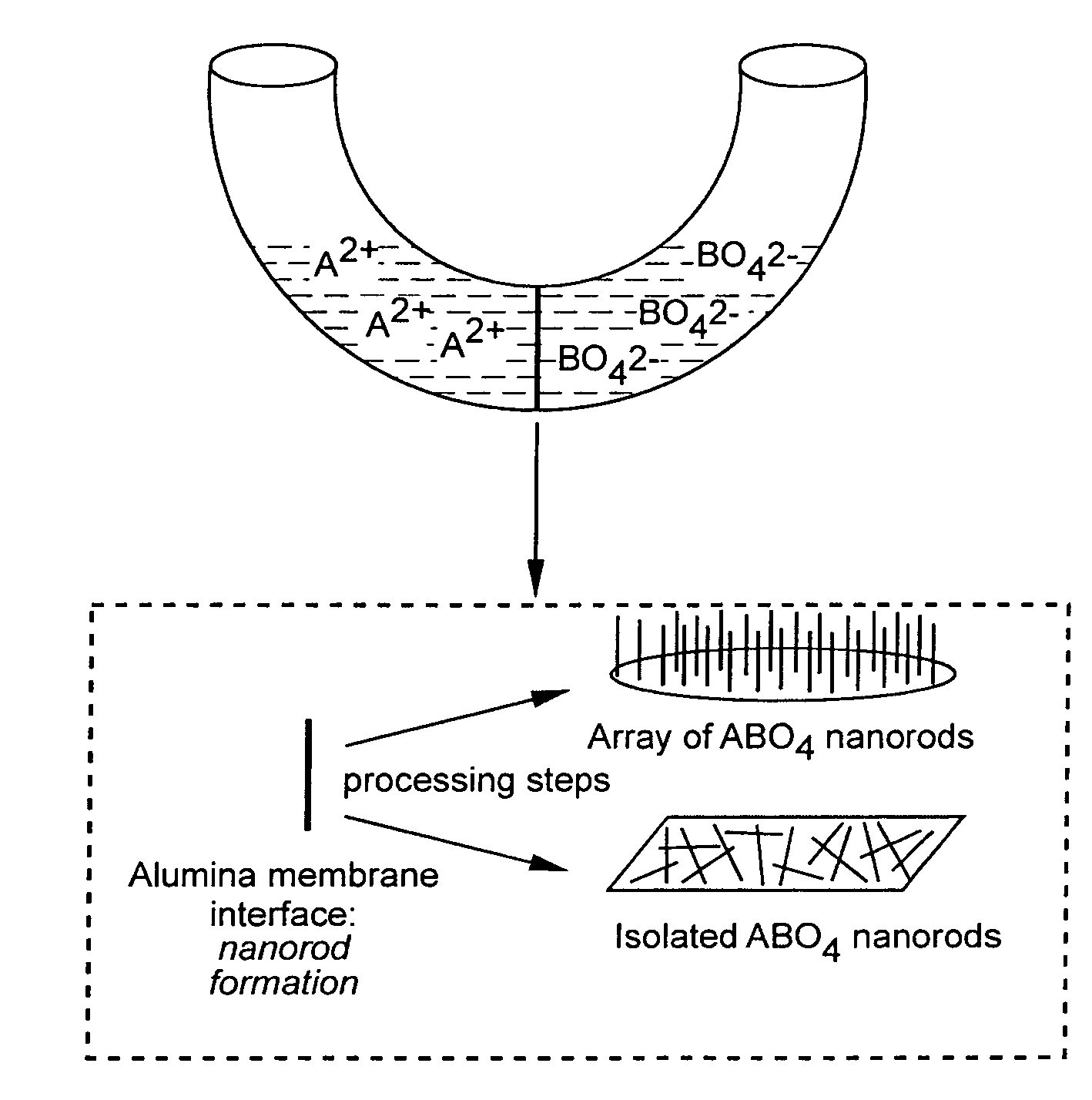
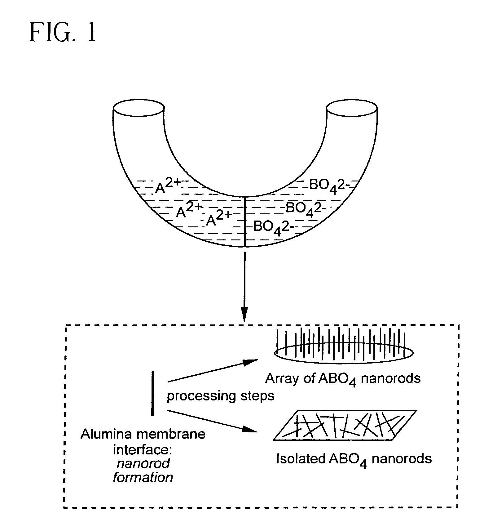
[0135]Materials Preparation. Alumina template membranes (Fisher Scientific) with pore sizes of 100 nm and 200 nm were prepared by a two-step aluminum anodic oxidation process. (See Schmid, G., J. Mater. Chem., 2002, 12, 1231 and Hulteen et al., J. Mater. Chem., 1997, 7, 1075, both incorporated herein by reference.) The membrane was initially hydrated by immersion and sonication in a small volume of distilled, deionized water for a few minutes, so as to avoid air bubble formation within its structure or on its surface. Subsequently, the membrane was mounted between the two halves of a U-tube cell. The half-cells were then filled with equimolar solutions of Ba(NO3)2 and either Na2WO4 or Na2CrO4 solutions to generate barium tungstate and chromate, respectively. After immersion times of up to 12 hours at room temperature, the alumina template, into which the precursors had presumably diffused resulting in product formation, was detached and thoroughly washed with deionized water. The al...

example 2

Materials Preparation

[0156]Commercially available polycarbonate membranes (Whatman Co., UK) used in this study contain pore sizes of 50, 100, and 200 nm diameter, respectively, with a thickness of ˜6 μm. These polycarbonate filters contain track-etched channels. Pores were randomly distributed across the filter membranes, and pore densities were quoted as approaching 3×10⁸ pores c−2. In order to avoid air bubble formation on their surface, the membranes were pre-hydrated by immersion and sonication in a small volume of distilled, deionized water for a few minutes. Subsequently, the membrane was placed between the two arms of a U-shaped tube (FIG. 17).

[0157]In the typical synthesis, each half cell was filled with a solution of 0.25 M NH4F and either 0.125 mM CaCl2, SrCl2, or Ba(NO3)2 solutions to generate calcium fluoride, strontium fluoride and barium fluoride nanowires, respectively. After immersion times of up to 12 hours at room temperature, the polycarbonate membrane was detache...


PUM

PropertyMeasurementUnit
aspect ratioaaaaaaaaaa
diameteraaaaaaaaaa
lengthaaaaaaaaaa

Abstract

The present invention includes pure single-crystalline metal oxide and metal fluoride nanostructures, and methods of making same. These nanostructures include nanorods and nanoarrays.

Description

CROSS-REFERENCE TO RELATED APPLICATION[0001]This application claims the benefit of U.S. Provisional Application No. 60 / 733,010, filed Nov. 2, 2005, which is incorporated herein by reference in its entirety.[0002]This invention was made with support by the US Department of Energy under contract number DE-AC02-98CH10886 and the National Science Foundation under CAREER award DMR-0348239. The Government has certain rights in this invention.BACKGROUND OF THE INVENTION[0003]Nanoscale structures, such as nanoparticles, nanorods, nanowires, nanocubes, and nanotubes, have attracted extensive synthetic attention as a result of their novel size-dependent properties (Xia et al., Adv. Mater., 2003, 15, 353; Patzke et al., Angew. Chem. Int. Ed., 2002, 41, 2446; Wu et al., Chem. Eur. J., 2002, 8, 1260; Tremel, W., Angew. Chem. Int. Ed., 1999, 38, 2175; Tenne, R., Chem. Eur. J., 2002, 8, 5296; Rao et al., J. Mater. Chem., 2001, 11, 2887; and Rao et al., J. Chem. Soc., Dalton Trans., 2003, (1), 1). ...

Claims


Application Information

Patent Timeline
Patent Type & Authority Patents(United States)
IPC IPC(8): C01F1/00C01F11/00C01F5/00C01G1/00C01G11/00C01G21/00C01G3/00C01G37/14C01G41/02C01G45/00C01G49/00C01G51/00C01G53/00C01G57/00C01G9/00C01G99/00
CPCB82Y30/00C30B7/14C30B29/62C30B29/24C30B29/22Y10S977/773Y10S977/895Y10S977/811Y10S977/812
Inventor WONG, STANISLAUS S.MAO, YUANBING
Owner THE RES FOUND OF STATE UNIV OF NEW YORK
Learn More