
Gas turbine power generating machine

a technology of power generation machine and gas turbine, which is applied in the direction of machines/engines, electric generator control, lighting and heating apparatus, etc., can solve the problems of not meeting the requirements of the above-described related art, the outturn is relatively small, and the profit is no longer expected. achieve the effect of effective utilization

Active Publication Date: 2009-09-01
MITSUBISHI POWER LTD
View PDF10 Cites 91 Cited by
  • Summary
  • Abstract
  • Description
  • Claims
  • Application Information

AI Technical Summary

Benefits of technology

The present invention provides a gas turbine power generating machine that can effectively utilize natural gas and liquid fuel produced from medium- or small-scaled gas fields and overage gas fields. The machine comprises a gaseous fuel processing apparatus for pre-processing natural gas, a liquid fuel processing apparatus for pre-processing liquid fuel, and a gas turbine. The machine can effectively utilize natural gas and liquid fuel that would have been left unused in the past, reducing costs and ensuring profitability. The machine also includes sensors and a control unit for optimizing fuel supply to the combustor based on detected gas temperature and power output. The technical effect of the invention is to provide a more efficient and cost-effective way to utilize gas and liquid fuel produced from small-scaled gas fields and overage gas fields.

Problems solved by technology

However, the above-described related art has problems as follows.
Also, in medium- or small-scaled gas fields and in gas fields that have become overage with the progress of gas extraction, outturn is relatively small and a profit is no longer expected because of an increase in cost of the fuel transporting system relative to the outturn.
For that reason, the natural gas (gaseous fuel) extracted from the medium- or small-scaled gas fields and the overage gas fields has not been transported to the consuming area and hence has not been effectively utilized.
Further, for liquid fuel such as associated oil produced concurrently during the extraction of natural gas and condensates (hydrocarbons being liquid at room temperature and atmospheric pressure) generated in the refining process of natural gas, it is hard to ensure a profit because of an increase in the fuel transporting cost as in the above-mentioned case.
Therefore, that liquid fuel has not also been effectively utilized.
In medium- or small-scaled oil fields and overage oil fields, it is similarly hard to ensure a profit because of an increase in the fuel transporting cost as in the above-mentioned gas fields.
Therefore, crude oil (liquid fuel) and gaseous fuel, such as associated gas produced concurrently during oil extraction, have not been effectively utilized in the past.

Method used


Image

  • Gas turbine power generating machine
  • Gas turbine power generating machine
  • Gas turbine power generating machine

Examples


Embodiment Construction

[0028]Embodiments of the present invention will be described below with reference to FIGS. 1-5.

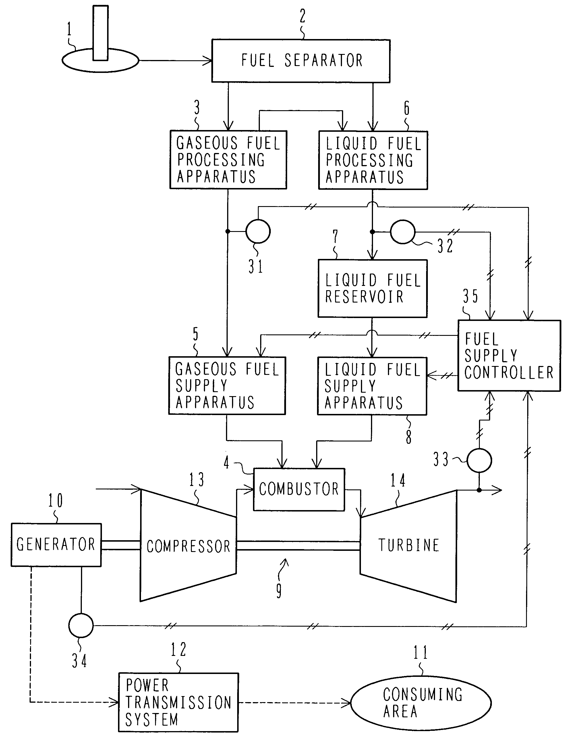
[0029]FIG. 1 is a block diagram showing an overall construction of the gas turbine power generating machine according to the first embodiment. Note that this first embodiment is described, by way of example, in connection with the case using natural gas (gaseous fuel) extracted from gas fields and liquid fuel produced during the extraction and refining process of the natural gas.

[0030]Referring to FIG. 1, the gas turbine power generating machine is installed near a gas field 1. The gas turbine power generating machine comprises a fuel separator 2 for separating natural gas (gaseous fuel) from liquid gas, such as associated oil produced concurrently during extraction of the natural, a gaseous fuel processing apparatus 3 for pre-processing the natural gas separated by the fuel separator 2 to be ready for combustion, a gaseous fuel supply apparatus 5 for supplying the gaseous fuel pre-process...


PUM


Abstract

The plant includes a gaseous fuel processing apparatus for pre-processing natural gas (gaseous fuel) produced in the gas field, a liquid fuel processing apparatus for pre-processing liquid fuel obtained during the extraction and refining process of the natural gas, and a gas turbine. The gas turbine includes a compressor for generating compressed air, a combustor for mixing the compressed air from the compressor with one or both of the gaseous fuel pre-processed by the gaseous fuel processing apparatus and the liquid fuel pre-processed by the liquid fuel processing apparatus, and for burning a gas mixture, and a turbine for driving a generator by combustion gases supplied from the combustor.

Description

BACKGROUND OF THE INVENTION[0001]1. Field of the Invention[0002]The present invention relates to a gas turbine power generating machine. More particularly, the present invention relates to a gas turbine power generating machine which is installed near gas fields or oil fields and which transmits generated electricity to a consuming area through a power transmission system.[0003]2. Description of the Related Art[0004]In view of environmental pollution in worldwide scale, regulations on exhaust gases from various engines have been urged in progress. Under such situations, natural gas is increasingly employed as fuel giving less influence upon environments. Natural gas produced in a gas field is transported to a consuming area, for example, by a method of liquefying the natural gas with a liquefaction facility near the gas field and transporting the liquefied natural gas to the consuming area by land or sea, or by a method of transporting the natural gas, as it is, to the consuming are...

Claims


Application Information

Patent Timeline
Patent Type & Authority Patents(United States)
IPC IPC(8): F02C3/20
CPCF01D15/10F02C3/20F23R3/36F02C3/24F23R3/343F02C3/22
Inventor YOSHIDA, SHOUHEIHIRATA, YOSHITAKAINOUE, HIROSHIKOBAYASHI, NARIYOSHI
Owner MITSUBISHI POWER LTD
Features
  • Generate Ideas
  • Intellectual Property
  • Life Sciences
  • Materials
  • Tech Scout
  • Unparalleled Data Quality
  • Higher Quality Content
  • 60% Fewer Hallucinations
Learn More