Isolated measurement circuit for sensor resistance

a technology of resistive sensor and isolation circuit, which is applied in the direction of heat measurement, mechanical actuation of burglar alarms, instruments, etc., can solve the problems of poor response, difficult to indicate a short circuit, and non-linearity of isolation transformers

Inactive Publication Date: 2009-09-22
ABB OY
View PDF13 Cites 31 Cited by
  • Summary
  • Abstract
  • Description
  • Claims
  • Application Information

AI Technical Summary

Benefits of technology

[0009]Applicants have disclosed measurement circuits that make it possible to measure sensor resistance over a wide resistance range, which enables the use of different types of sensors while still providing a reliable indication of a short circuit or break in the sensor circuit. The disclosed measurement circuit can also be used in situations where high voltage strength (insulation level) is required between the sensor circuit and SELV electronics.
[0013]The frequency of the sawtooth generator can be low, because the time constants of the object of measurement, which are in the order of more than one second, allow for a long response time for the measurement result. This makes it possible to use inexpensive opto-isolators. In order to manage resolution over a wide range of resistance measurement (50Ω . . . 15 kΩ), the intention is to imitate logarithmic response with an amplifier circuit that is as simple as possible. The more the voltage over the sensor increases, the more the amplifier reduces the voltage supplied to the voltage divider circuit. This means that a better resolution is achieved at lower resistance values, which facilitates the indication of a short circuit in the sensor circuit.
[0016]An exemplary arrangement can allow a wide measurement range, for example 50Ω . . . 15 kΩ, and can be most sensitive in the 1 kΩ . . . 5 kΩ range, which covers the threshold levels of the most common PTC or NTC thermistors. The feedback block used in the solution according to the invention makes it possible to achieve sufficient selectivity for the detection of fault situations—including a short circuit as well as an open circuit. The disclosed embodiments makes it possible to achieve a lower price and easier calibration compared with solutions implemented using a linear opto-isolator. Calibration can be carried out reliably using no more than two measurement points. Another aspect of the disclosed embodiments is that due to the supply voltage feedback block used, the voltage over the sensor resistance is very low, less than 2 V, and it is preferably supplied to the sensor through a series resistor in the order of 20 kΩ. This means that it is very safe to locate the thermistor sensor connected to the circuit within an explosive Ex atmosphere because it remains clearly below the critical levels for electric sparking. The low-frequency PWM technology can be used to enable the use of slightly slower opto-isolators with a high isolation voltage strength. The reliability of opto-isolator operation in long-term use is crucial, so the opto-isolator must be selected from sufficiently high-quality components proportioned to the application.

Problems solved by technology

A disadvantage of this solution is the non-linearity of the isolation transformer and its poor response, particularly at low sensor resistance values, which makes it difficult to indicate a short circuit.
Another disadvantage is the effect of capacitance in the sensor circuit conductors, which is summed to the measurement circuit through the isolation transformer in addition to the actual effect of the sensor resistance.
Another conventional solution is the use of a linear opto-isolator, but this causes problems due to the high price of the component and large differences in tolerance between the individual components, which makes the implementation of calibration for the measurement circuit complicated.
Reliability and stability in long-term use are poor as well.
The solution can be inexpensive, but its disadvantage is the ON / OFF type status information; no information is available on the state of change in the resistance value—for example, whether it is approaching the threshold value slowly or rapidly.
The chip converts the resistance value of each sensor to one Pulse Width Modulated (PWM) pulse; however, the range of the pulse ratio is quite narrow.
The linear operation of the circuit makes it difficult to distinguish a short circuit from small values of resistance.
The measurement range can be adjusted using a resistance connected in series with the sensor, but the usable measurement range in each case is too restricted with regard to an application for measuring the temperature of electric motor windings and protecting them.
There is no second-source manufacturer of the chip, which means that it will bind the user to a single component supplier.
Due to its physical size and limited operating temperature range, the chip is not applicable to the protection of electric motor windings.
The PWM frequency of the chip output is 1 . . . 4 kHz, which also sets excessively tight requirements for the interface component and the circuits for analysing the measurement result.
The isolation of a digital signal using an opto-isolator is a better method than the isolation of an analogue signal using a linear opto-isolator with poorer long-term stability.

Method used


Image

  • Isolated measurement circuit for sensor resistance
  • Isolated measurement circuit for sensor resistance
  • Isolated measurement circuit for sensor resistance

Examples


Embodiment Construction

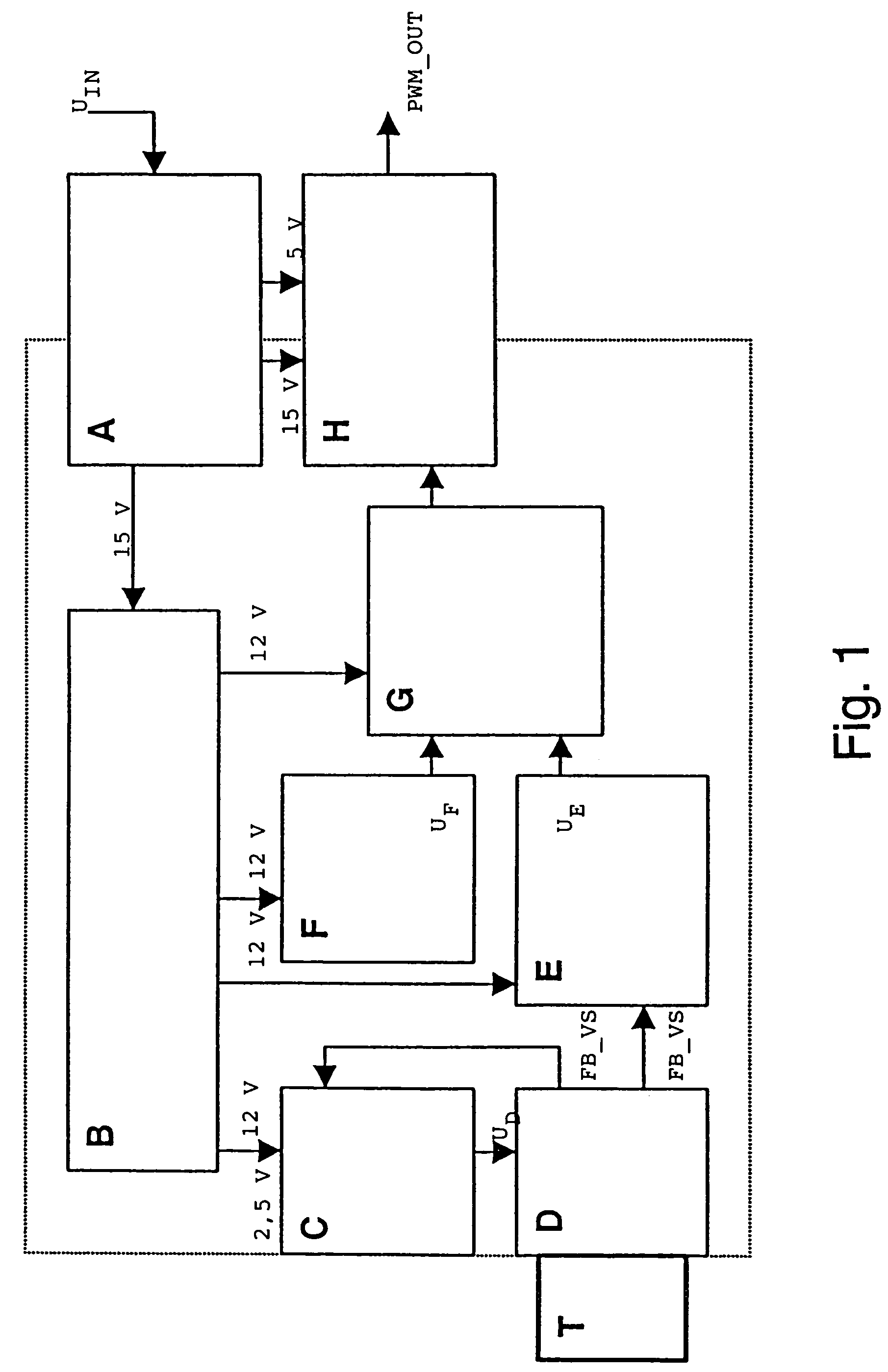
[0024]FIG. 1 illustrates an exemplary sensor measurement electronic circuit as a block diagram. The dotted line limits the area of isolated measurement electronics, with a SELV electronic circuit on the outside.

[0025]An exemplary block A comprises a secondary winding of triple-insulated wire added to the ferrite transformer in a DC / DC switching-mode power supply that is already included in the measurement device. This provides the isolated measurement electronics with the required electric power, typically 15 V, 10 mA. Other power supply configurations with the required insulating strength can also be used.

[0026]An exemplary block B includes means for generating a regulated DC voltage, such as 12 V, for supplying the measurement electronics; this can be a shunt regulator with associated components.

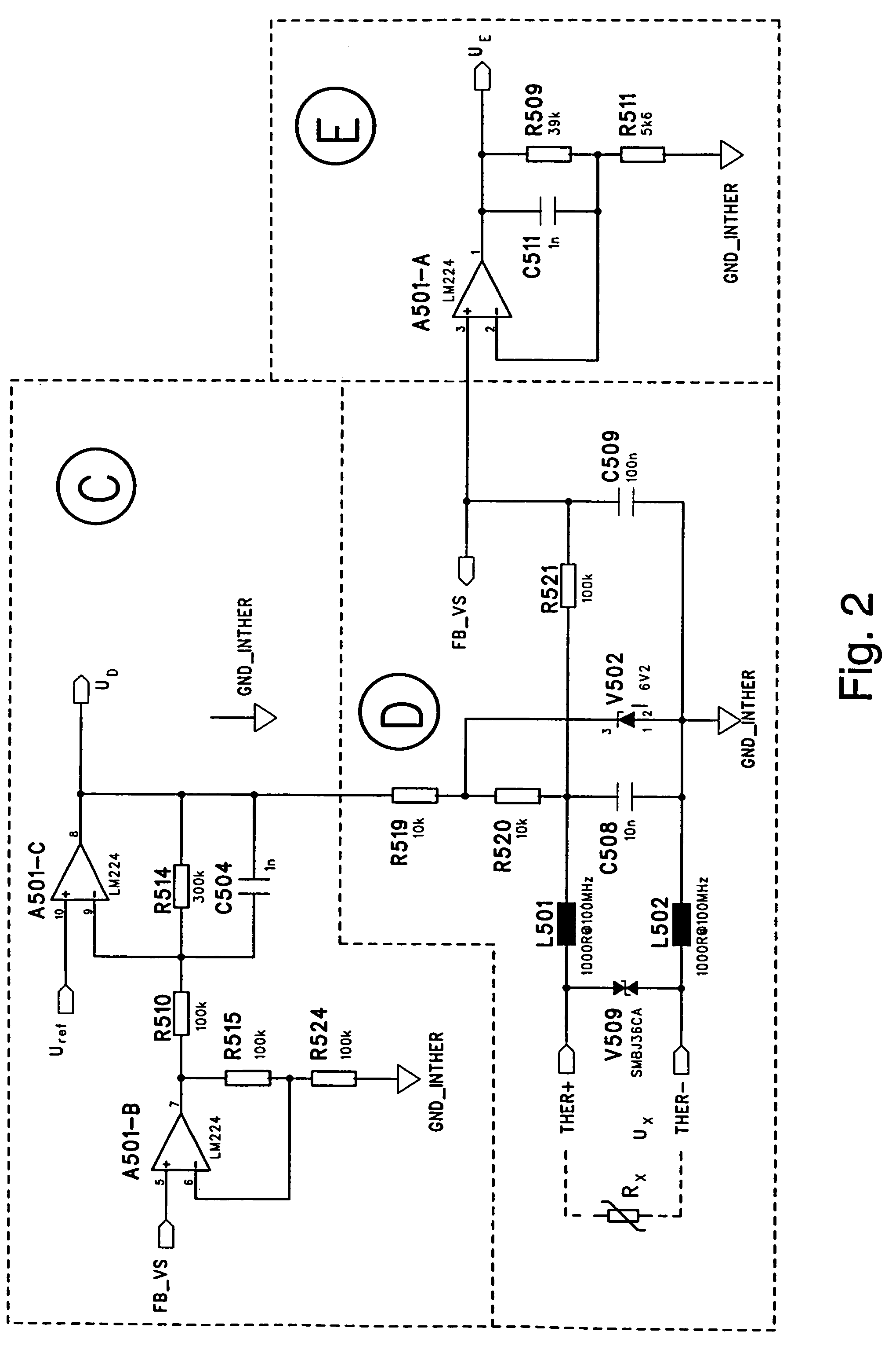
[0027]An exemplary block C comprises an amplifier stage in a feedback configuration that supplies a DC voltage (UD) to the sensor circuit so that when sensor resistance (Rx) increases, the...


PUM

PropertyMeasurementUnit
frequencyaaaaaaaaaa
resistanceaaaaaaaaaa
temperaturesaaaaaaaaaa

Abstract

A circuit and method is disclosed for measuring the resistance of a resistive sensor, such as a PTC or NTC temperature sensor used for monitoring the temperature of the windings of an electric motor. The measurement circuit is based on an electronic circuit in which conductors from a sensor located in the object to be monitored are connected to an amplifier circuit in a feedback configuration that reduces the DC level supplied to the voltage divider when the sensor resistance increases. The measured signal is amplified and, using a comparator to compare it with the output voltage of a sawtooth generator, a continuous PWM (Pulse Width Modulation) signal is generated and transmitted in digital format to a SELV electronic circuit, for example through an opto-isolator. The essentially logarithmic signal amplification makes it possible to reliably distinguish between a short circuit in the sensor circuit and low values of sensor resistance.

Description

CROSS REFERENCE TO RELATED APPLICATIONS[0001]This application claims priority under 35 U.S.C. §119 to Finnish Application FI20040802 filed in Finland on 10 Jun. 2004, and as a continuation application under 35 U.S.C. §120 to PCT / FI2005 / 000267 filed as an International Application on 8 Jun. 2005 designating the U.S., the entire contents of which are hereby incorporated by reference in their entireties.FIELD[0002]The disclosure relates to measuring the resistance of a resistive sensor, such as a PTC or NTC thermistor sensor used for monitoring the temperature of electrical machines, such as the windings of a squirrel cage motor.BACKGROUND INFORMATION[0003]In addition to protection of a squirrel cage motor based on current measurement, thermistor sensors can be used to protect windings against overheating, for example when the ambient temperature rises or motor cooling is insufficient for any reason. When a squirrel cage motor is used in an explosive atmosphere (Exe), the regulations r...

Claims


Application Information

Patent Timeline
Patent Type & Authority Patents(United States)
IPC IPC(8): G01R27/08G01K7/16G01K7/22G01K7/24G01K7/25H02HH02H1/00H02H7/085
CPCG01K7/24H02H7/0852G01K7/25
Inventor LAAKSO, KARI-MATTIBERTS, ANDREAS
Owner ABB OY
Why Eureka
Try Eureka