
Process for making lube oil basestocks

a technology of lubricating oil basestocks and base oils, which is applied in the direction of hydrocarbon oil treatment products, physical/chemical process catalysts, metal/metal-oxide/metal-hydroxide catalysts, etc., can solve the problems of increasing the proportion of naphthenic and asphaltic base crudes, increasing the difficulty of meeting the demand for lubricating oil basestocks or base oils, and involving expensive operating conditions and low yields

Active Publication Date: 2009-10-06
EXXON RES & ENG CO
View PDF50 Cites 14 Cited by
  • Summary
  • Abstract
  • Description
  • Claims
  • Application Information

AI Technical Summary

Benefits of technology

The present invention provides a process for preparing lubricating oil basestocks with a viscosity index of about 80 to 120 from a lube oil boiling range feedstock. The process involves extracting the feedstock with a solvent, contacting it with a hydrotreating catalyst system to produce a hydrotreated effluent, and then removing a portion of the solvent to produce a raffinate. The raffinate is then dewaxed to produce the desired lubricating oil basestock. The process can be used with different types of lube oil feedstocks, such as dewaxed oil or automatic transmission fluid. The resulting lubricating oil basestocks have a desirable combination of properties, including a high viscosity index, low sulfur content, and low viscosity index.

Problems solved by technology

However, with the decline in the availability of paraffinic base crudes, and a corresponding increase in the proportion of naphthenic and asphaltic base crudes, it is becoming increasingly difficult to meet the demand for lubricating oil basestocks, or base oils.
Conventional techniques for preparing basestocks such as hydrocracking or solvent extraction require severe operating conditions such as high pressure and temperature or high solvent:oil ratios and high extraction temperatures to reach these higher basestock qualities.
Either alternative involves expensive operating conditions and low yields.
However, this combination also results in decreased yields of lubricating oils due to the conversion to distillates that typically accompany the hydrocracking process.

Method used


Image

  • Process for making lube oil basestocks
  • Process for making lube oil basestocks

Examples


example 1

[0058]A medium vacuum gas oil having the properties outlined in Table 1 was processed in an isothermal pilot plant over three catalysts systems at 1200 psig hydrogen partial pressure. The catalyst systems and operating conditions are given in Table 2. Catalyst B is a conventional hydrotreating catalyst having about 4.5 wt. % Group VI metal, about 23 wt. % Group VIII metal on an alumina support and has an average pore size of 14.0 nm. The bulk metal hydrotreating catalyst was a commercial bulk metal hydrotreating catalyst marketed under the name Nebula by Akzo-Nobel.

[0059]In the Examples, all the catalyst systems were lined out at about 50 days on stream. A first order kinetic model with an activation energy of 31,000 cal / gmol was used to compare volume activities between the catalysts.

[0060]

TABLE 1Medium Vacuum Gas OilDensity at 70° C. (g / cc)0.88Nitrogen (wppm)700Sulfur (wt. %)2.6GCD 5 WT % Boiling Point (° C.)334GCD 50 WT % Boiling Point (° C.)441GCD 95 WT % Boiling Point (° C.)531...

example 2

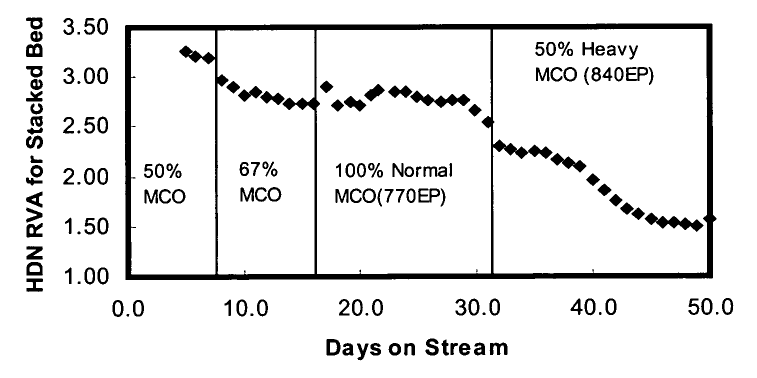
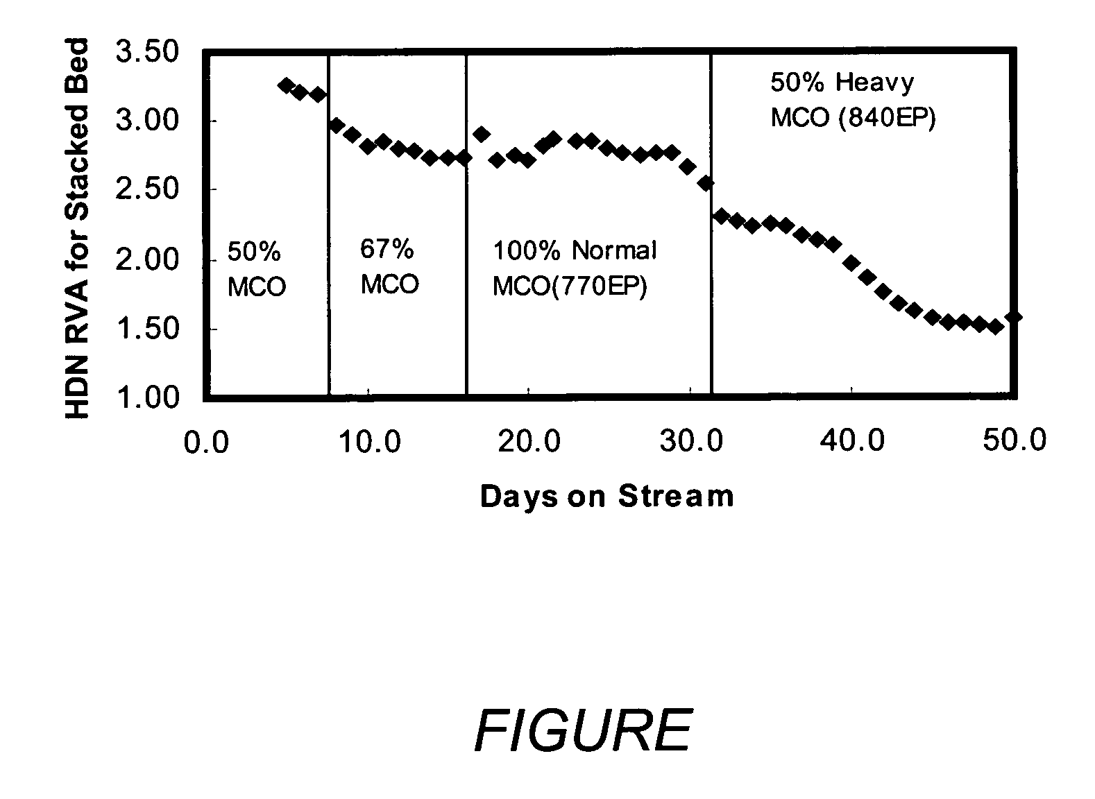
[0063]The hydrotreating ability of different stacked beds of Catalyst B and Nebula were analyzed by hydrotreating different feedstreams over the stacked beds in the in two parallel reactor trains of the same isothermal pilot plant unit used in Example 1 above. The feedstreams used were Medium Cycle Oils (“MCO”) from an FCC unit and blends of the MCO with a virgin feedstock were tested in two parallel reactor trains. The feed properties are described in Table 3, below.

[0064]In this Example, one reactor train consisted entirely of a conventional NiMo on Alumina hydrotreating catalyst, Catalyst C, with an average pore diameter of 7.5 nm. The other reactor train contained a stacked bed system with 75-vol. % of Catalyst C followed by 25-vol. % of Catalyst A, a bulk multimetallic sulfide catalyst having an average pore diameter of 5.5 nm.

[0065]The separate reactors in both trains were immersed in a fluidized sandbath for efficient heat transfer. Thus, the temperature of the first 75-vol. ...

example 3

[0071]In this Example, a stacked bed catalyst system containing 75 vol. % of Catalyst B and 25 vol. % Nebula, both as described above, was used to hydrotreat a light cycle cat oil feed (“Feed A”) and a heavier medium cycle cat oil feed (“Feed B”) as described in Table 5 below. Example 2 was conducted in the same two reactor train pilot plant unit as described in Example 2 above. The operating conditions for the two trains were 1200 psig H2, liquid hourly space velocities of 2 vol. / hr / vol., and 5000 SCF / B of hydrogen.

[0072]The reactor effluents were stripped with nitrogen in an oven at 100° C. to remove substantially all of the gaseous reaction products. The nitrogen content of the liquid reactor effluent was then analyzed by ASTM 4629. The temperature schedules for both trains along with the results of this example are described in Table 5 below.

[0073]

TABLE 5FEEDFeed AFeed BAPI Gravity0.9730.9Sulfur, wt. %2.62.50Nitrogen, ppm713742Distillation, D2887 GCD 54274485055159095707755EP764...


PUM


Abstract

A process for producing lube oil basestocks involving solvent extracting a waxy feed to produce at least a lube oil boiling range raffinate, hydrotreating the lube oil raffinate to produce a hydrotreated raffinate, and dewaxing the hydrotreated raffinate.

Description

CROSS-REFERENCE TO RELATED APPLICATIONS[0001]This application claims benefit of U.S. Provisional Patent Application Ser. No. 60 / 518,739 filed Nov. 10, 2003 and Ser. No. 60 / 608,466 filed Sep. 9, 2004.FIELD OF THE INVENTION[0002]The present invention relates to a process for preparing lubricating oil basestocks from lube oil boiling range feedstreams that meet American Petroleum Institute Group II specifications. More particularly, the present invention is directed at a process wherein a wax containing feedstock is solvent extracted to produce at least a lube oil boiling range raffinate, the lube oil raffinate is hydrotreated to produce a hydrotreated raffinate, and the hydrotreated raffinate is dewaxed.BACKGROUND OF THE INVENTION[0003]It has long been recognized that one of the most valuable products generated through the refining of crude mineral oils is lubricating oils. It is common practice to recover lubricating oil basestocks by solvent extracting, with a selective solvent, und...

Claims


Application Information

Patent Timeline
Patent Type & Authority Patents(United States)
IPC IPC(8): C10G73/38C10G65/02C10G67/04B01J23/00B01J23/85B01J23/882B01J23/883B01J23/888B01J35/00B01J35/10B01J37/20C10G45/04C10G45/60C10G49/00C10G65/04
CPCB01J23/85B01J23/8885B01J35/0006B01J35/10C10G49/002C10G2300/44B01J23/883B01J35/1019B01J35/1033B01J35/1061B01J37/20C10G2400/10C10G2300/4018C10G2300/1022C10G2300/1062C10G2300/1074C10G2300/202C10G2300/301C10G2300/302B01J23/882B01J35/19B01J35/60B01J35/63B01J35/647B01J35/615B01J35/00C10G67/04
Inventor SCHLEICHER, GARY P.RILEY, KENNETH L.STAVENS, ELIZABETHHANTZER, SYLVAIN
Owner EXXON RES & ENG CO
Learn More