Manipulator with automatic control, especially for the food industry

a technology of automatic control and manipulator, which is applied in the direction of manual control with multiple controlling members, manual control with single controlled members, mechanical control devices, etc., can solve the problems of increased manufacturing costs, contamination of and/or damage to robots, and the addition of additional parts of robots such as the robot arm or the robot hand, which are not protected

Inactive Publication Date: 2009-10-20
KUKA ROBOTER
View PDF13 Cites 15 Cited by
  • Summary
  • Abstract
  • Description
  • Claims
  • Application Information

AI Technical Summary

Benefits of technology

[0007]The basic object of the present invention is to provide an automatic manipulator that can be used in an environment in which there is a risk for contamination and that reliably avoids the above-described drawbacks.
[0009]Since the support structure of the automatic manipulator itself is made of stainless steel it exhibits passive and high resistance to corrosive attack by organic acids, weak mineral acids and atmospheric oxidation. This eliminates the additional and costly application of coverings, coatings, envelopes or the like for avoiding contamination, so that the automatic manipulator according to the present invention can also be used under conditions under which high hygienic requirements are to be met, as in the food industry or the pharmaceutical industry. A preferred variant of the automatic manipulator according to the present invention makes therefore provisions for the support structure to be made of a material that is suitable for use in contact with foods. According to an extremely preferred variant of the present invention, the support structure is made of stainless steel.
[0010]To prevent dirt, moisture or the like from accumulating in cavities of the support structure and foci of contamination, such as nests of bacteria or the like from forming, provisions are, furthermore, additionally made in a preferred embodiment for hermetically sealing cavities of the support structure that are dictated by the design by welding together, for example, two or more partial shells of the automatic manipulator, which form a support part, such as the robot arm or the rocker, or by bracing them against each other with the arrangement of a seal. The support part may preferably also be cast as a one-piece part, in which case only the opening for removing the casting core is to be closed by a cover. “Hermetically closed” always means, in particularly, a fluid-tight sealing, which reliably prevents both contaminants from escaping from the automatic manipulator to the outside into the environment and the entry of ambient air into the automatic manipulator, so that no foci of contamination, such as nests of bacteria or deposits of dirt, etc., can be formed there.

Problems solved by technology

Such contamination is caused, on the one hand, by lubricant or abraded particles, which are released from the interior the robot and enter the environment.
On the other hand, the robot is always contaminated in the working areas from the outside, for example, by food residues and / or moisture, which may lead to contamination of and / or damage to the robot.
The fact that the covering provided additionally represents an extra design effort (in terms of the material), which is associated with correspondingly increased manufacturing costs, shall be considered to be particularly disadvantageous in such a solution.
In addition, additional parts of the robot, such as the rocker, the robot arm or the robot hand, continue to be unprotected, and they represent a potential risk for contamination.
The additional step of coating the robot represents a disadvantageous extra cost for preparing the coating in this case as well.
Furthermore, the protective action of such a coating may decline over time and after repeated cleaning operations, e.g., with high-pressure cleaning devices.
Moreover, a local damage to the protective coating is possible.

Method used


Image

  • Manipulator with automatic control, especially for the food industry
  • Manipulator with automatic control, especially for the food industry

Examples


Embodiment Construction

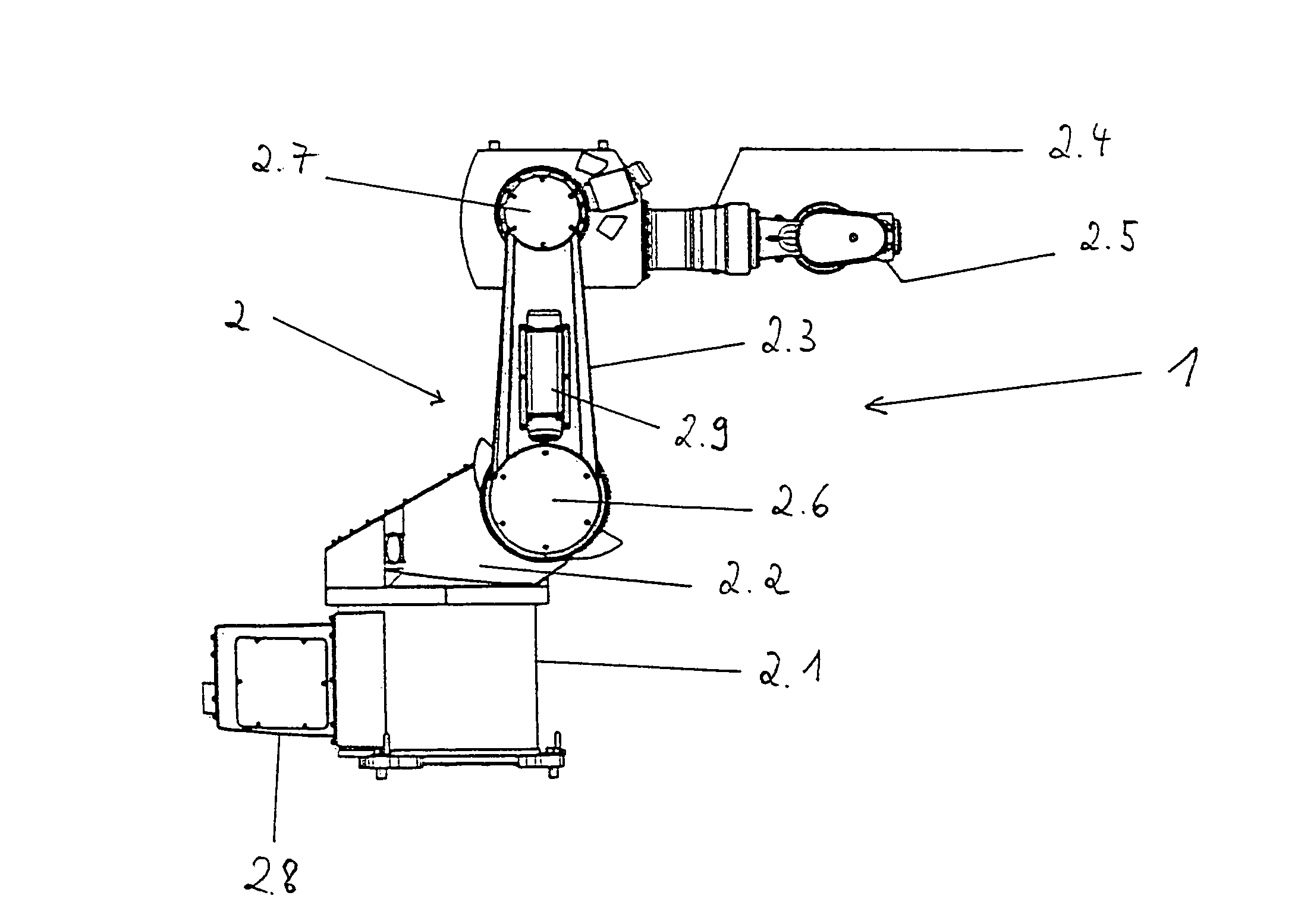
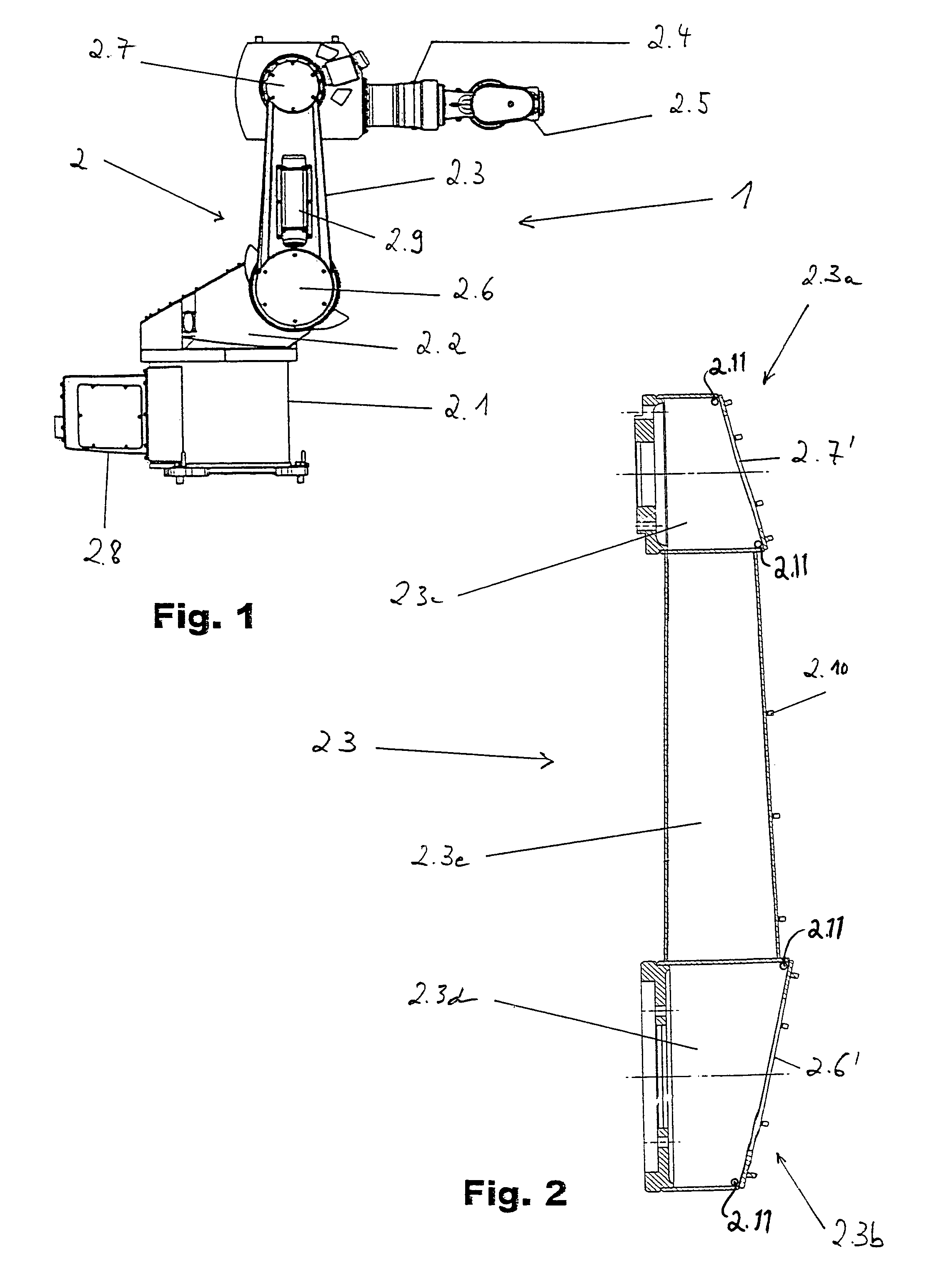
[0017]FIG. 1 shows a side view of an embodiment of an automatic manipulator according to the present invention in the form of a multiaxial industrial robot 1, especially according to the standard EN ISO 8373. The robot 1 has a support structure 2 with a frame 2.1, a carousel 2.2, a rocker 2.3, an arm 2.4 and a hand 2.5, which is manufactured according to the present invention completely of a material that is resistant to external effects, such as moisture or the like, for example, stainless steel. The support structure 2 is thereby formed from a material that is suitable for use in contact with foods. That is, the material is resistant so as not to react with the environment (moisture, oxygen) and the material does not poison food or otherwise make the food unfit for human consumption upon contact of the food with the material. The food does not corrode the material and the material does not react with organic material. Dirt or soiling of the robot by food may easily be removed. Acc...


PUM


Abstract

An automatic manipulator, such as a multiaxial industrial robot, with a carrying component structure (support structure) for transmitting forces between individual members of the automatic manipulator. The entire support structure is formed from a material that is resistant with respect to external effects, such as moisture or the like. The material of the support structure may be, in particular, a material that is suitable for use in contact with foods, such as stainless steel, so that the automatic manipulator according to the present invention can be used reliably and without additional costly protective measures in environments in which there is a risk for contamination, such as in the food industry.

Description

CROSS REFERENCE TO RELATED APPLICATIONS[0001]This application claims the benefit of priority under 35 U.S.C. § 119 of German patent application DE 103 50 801.5 filed Oct. 29, 2003 the entire contents of which are incorporated herein by reference.FIELD OF THE INVENTION[0002]The present invention pertains to a handling gear or manipulator with automatic control according to EN ISO 8373, especially a multiaxial industrial robot, with a carrying component structure (support structure) for transmitting forces between individual members of the automatic manipulator. The present invention pertains, in particular, to an automatic automatic manipulator, such as a manipulator with automatic control according to EN ISO 8373.BACKGROUND OF THE INVENTION[0003]Automatic automatic manipulator of the above-described type, such as multiaxial industrial robots, hereinafter called robots for short, are regularly used in the food industry and the pharmaceutical industry, as in many other branches of ind...

Claims


Application Information

Patent Timeline
Patent Type & Authority Patents(United States)
IPC IPC(8): B25J17/00B25J19/00
CPCB25J19/0075Y10T74/20305
Inventor MARKERT, JOACHIMMERK, GUNTHER
Owner KUKA ROBOTER
Why Eureka
Try Eureka