Hybrid vehicle controller

a hybrid vehicle and controller technology, applied in the field of hybrid vehicles, can solve the problems of torque shocks felt by drivers, further increase in power consumption of high-voltage batteries, so as to improve the engine startup capability and reduce the capacity of high-voltage batteries mounted

Inactive Publication Date: 2009-10-27
DENSO CORP
View PDF23 Cites 28 Cited by
  • Summary
  • Abstract
  • Description
  • Claims
  • Application Information

AI Technical Summary

Benefits of technology

[0008]The present invention provides a hybrid vehicle controller which can prevent changes in crank position of the internal combustion engine to improve the startup capability of the engine while the vehicle is running in the motor drive mode in which only the motor is used to drive the vehicle. Furthermore, the present invention provides a hybrid vehicle controller which can satisfy the requirements for reducing the capacity of the high-voltage battery mounted in the vehicle.
[0009]One aspect of the present invention provides a controller for a hybrid vehicle. The hybrid vehicle includes an internal combustion engine and a motor, which are provided as power sources for driving the traction wheels of the vehicle. Also included are power split means for splitting the crankshaft power of the internal combustion engine into two drivelines to drive the traction wheels of the vehicle using one of the drivelines, and a generator coupled to the other driveline of the power split means. During the operation of the motor, the torque of the motor acts upon the one of the drivelines of the power split means to drive the traction wheels of the vehicle. The controller allows motor drive mode determination means to determine whether the vehicle is in a motor drive mode in which only the motor is used to drive the vehicle with the internal combustion engine at rest. If it is determined that the vehicle is in the motor drive mode, then the controller allows control means to control the torque produced in the generator so that the torque to act upon the crankshaft from outside the internal combustion engine is generally zero. During operation in the motor drive mode (with the internal combustion engine at rest), this arrangement allows the torque produced in the generator to be controlled so that the torque to act upon the crankshaft from outside the internal combustion engine is generally zero. Accordingly, in the motor drive mode (with the internal combustion engine at rest), it is possible to prevent the crank position of the internal combustion engine from being dislocated from a suitable startup crank position. It is thus made possible to improve the startup capability of the internal combustion engine as well as to eliminate an increase in power consumption in the high-voltage battery which conventionally resulted from degradation in startup capability. Thus, the controller can satisfy the requirements for reducing the capacity of the high-voltage battery mounted in the vehicle.
[0010]According to another aspect of the present invention, the control means of the controller may also include vehicle speed change detection means and generator torque command value computation means. More specifically, to control the torque produced in the generator, the vehicle speed change detection means senses a change in vehicle speed, and then the generator torque command value computation means computes a torque command value for the generator based on the change in vehicle speed (i.e., acceleration). When the motor drive mode determination means has determined that the vehicle is in the motor drive mode, the torque produced in the generator is controlled based on the torque command value for the generator. Thus, the controller may provide control so that the torque to act upon the crankshaft from outside the internal combustion engine is generally zero. In other words, while the generator is rotating at a speed corresponding to a running speed of the hybrid vehicle (the rotational speed of the driveshaft of the traction wheels), a change in the running speed would correspondingly change the speed of the generator, thereby causing generator inertial torque to act upon the crankshaft of the internal combustion engine. It is thus possible to compute the generator inertial torque acting upon the crankshaft of the internal combustion engine in accordance with a change in vehicle speed (or a change in generator speed). From this relationship, it is possible to set the torque command value for the generator to a value corresponding to the generator inertial torque in accordance with the change in vehicle speed (acceleration), thereby providing control such that the torque to act upon the crankshaft is generally zero. At this time, the inertial torque of the power split means can also be taken into account in addition to the generator inertial torque, thereby making the torque to act upon the crankshaft closer to zero with improved accuracy.
[0011]According to still another aspect of the present invention, the control means may also include generator speed change detection means to take it into account that a change in generator speed occurs in response to a change in vehicle speed (i.e., change in speed of the wheel driveshaft). More specifically, the generator speed change detection means may sense a change in generator speed, and then the torque command value for the generator may be set to a value corresponding to the generator inertial torque based on the change in generator speed, thereby providing control such that the torque to act upon the crankshaft is generally zero.
[0012]Alternatively, in a system which has the power split means configured to include a planetary gear mechanism with at least a planetary gear, the torque command value for the generator may also be set by considering the inertial torque of the power split means in addition to the generator inertial torque. In this case, the generator speed change detection means senses a change in generator speed, and motor speed change detection means senses a change in motor speed. Then, rotational speed change computation means computes a change in rotational speed of the planetary gear on its axis based on the changes in motor speed and generator speed. Based on the change in generator speed and the change in rotational speed of the planetary gear on its axis, the torque command value for the generator is then set to a value corresponding to the inertial torque of both the generator and the power split means. Control may be thus provided so that the torque to act upon the crankshaft is generally zero. In other words, the generator inertial torque can be computed once a change in generator speed is known, and likewise, the inertial torque of the planetary gear (the power split means) can be computed once a change in rotational speed of the planetary gear on its axis is known. Accordingly, this makes it possible to set the torque command value for the generator to a sum of the inertial torque of both the generator and the planetary gear in accordance with the changes in speed of the generator and in rotational speed of the planetary gear on its axis. It is thus possible to make the torque to act upon the crankshaft closer to zero with improved accuracy.

Problems solved by technology

Thus, with no countermeasures taken against this, changes would occur in vehicle drive torque causing the driver to feel torque shocks.
When the internal combustion engine is started using the generator but not smoothly, such a system will experience motoring by the generator or increase in time for torque canceling by the motor, resulting in an increase in power consumption in the high-voltage battery.
On the other hand, during the startup, the running drive power in the motor drive mode is sourced only from the high-voltage battery energy, thereby causing a further increase in power consumption in the high-voltage battery.
This in turn may make it necessary to limit the running drive power in the motor drive mode depending on the capacity of the high-voltage battery, causing the driver to feel lack in power.
Accordingly, it is a critical technical issue to provide an improved startup capability for the internal combustion engine of a split-type hybrid vehicle.
Applying the technique disclosed in this patent document mentioned above to the split-type hybrid vehicle may raise the following problems.
However, when only the motor is used to drive the vehicle, a planetary gear mechanism coupling between the motor and the generator would cause the planetary gear of the planetary gear mechanism to rotate (on its axis) depending on the running speed, thereby causing the generator to rotate.
This may result in degradation in startup capability, thereby causing an increase in power consumption in the high-voltage battery.
As described above, it will be thus necessary to limit the running drive power provided only by the motor, thereby causing the driver to feel lack in power.
From the viewpoint of reduction in battery costs and vehicle weight, this problem will become more noticeable as the high-voltage battery mounted in the vehicle is reduced in capacity.

Method used


Image

  • Hybrid vehicle controller
  • Hybrid vehicle controller
  • Hybrid vehicle controller

Examples


first embodiment

[0019]the invention will be described below with reference to FIGS. 1 and 2.

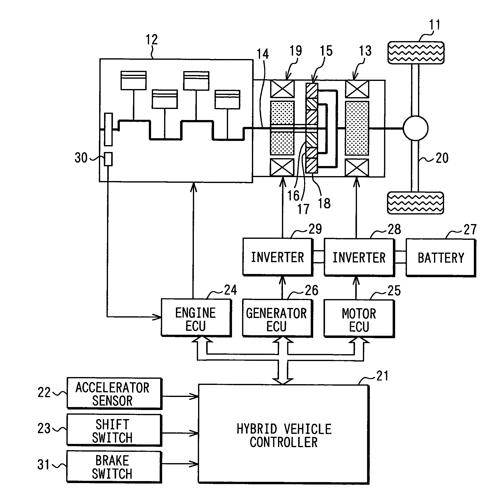
[0020]First, a drive system of a split-type hybrid vehicle will be described with reference to FIG. 1. As a power source for driving traction wheels 11 of the hybrid vehicle, the hybrid vehicle includes an engine 12 (an internal combustion engine) and a motor 13 (a motor generator). The power of a crankshaft 14 of the engine 12 is split into two drivelines through a planetary gear mechanism 15 which serves as power split means. The planetary gear mechanism 15 includes a sun gear 16 rotating at the center, a planetary gear 17 rotating on its axis and along the outer circumference of the sun gear 16, and a ring gear 18 rotating along the outer circumference of the planetary gear 17. The planetary gear 17 is coupled with the crankshaft 14 of the engine 12 via a carrier (not shown), the ring gear 18 being coupled with the rotational shaft of the motor 13, and the sun gear 16 being coupled with a generator 19 (a ...

second embodiment

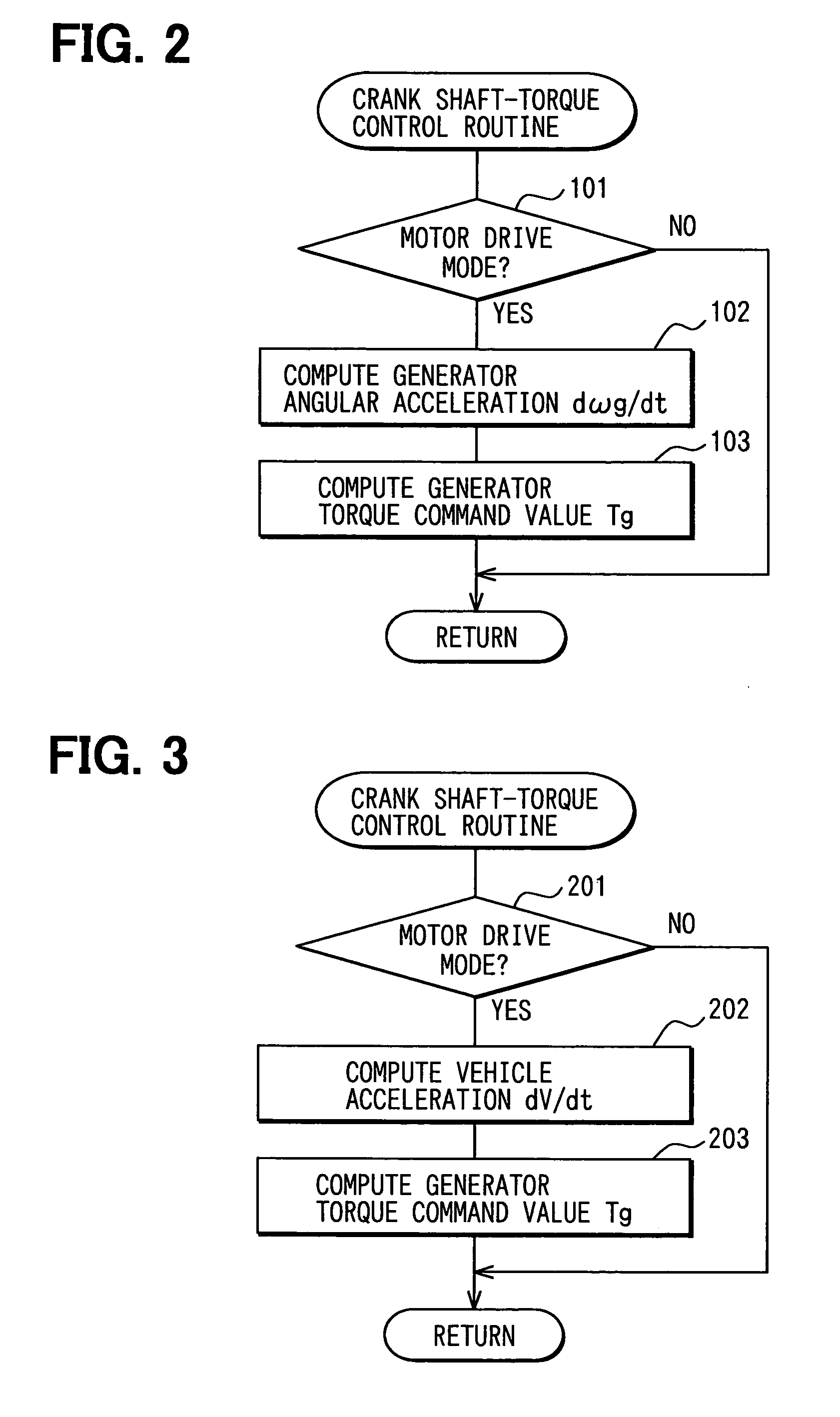
[0035]The second embodiment follows a crankshaft-torque control routine of FIG. 3. In step 201, if the routine determines that the vehicle is currently in the motor drive mode, the routine proceeds to step 202, where a vehicle acceleration dV / dt indicative of a change in speed of the vehicle is computed. The vehicle acceleration dV / dt can be obtained by calculating over time a change in vehicle speed V sensed by a vehicle speed sensor (not shown). The processing performed in the step 202 serves as the vehicle speed change detection means which is defined in the appended claim.

[0036]Thereafter, the routine proceeds to step 203, where the inertia Jg of the generator 19 is multiplied by the vehicle acceleration dV / dt and a coefficient C to find the generator torque command value Tg by

Tg=Jg×C×dV / dt,

where C is the coefficient for converting the vehicle acceleration dV / dt into the angular acceleration dωg / dt of the generator 19.

[0037]The second embodiment described above can also provide...

third embodiment

[0039]The third embodiment follows a crankshaft-torque control routine of FIG. 4. In step 301, if the routine determines that the vehicle is currently in the motor drive mode, the routine proceeds to step 302, where the rotation sensor or the like senses an angular speed of the motor 13 (motor speed) ωm. Then, in step 303, the angular acceleration dωm / dt of the motor 13 is computed. The processing performed in the step 303 serves as the motor speed change detection means which is defined in the appended claim. Thereafter, the routine proceeds to step 304, where an angular speed of the generator 19 (generator speed) ωg is sensed. Then, in step 305, the angular acceleration dωg / dt of the generator 19 is computed. The processing performed in the step 305 serves as the generator speed change detection means which is defined in the appended claim.

[0040]Thereafter, the routine proceeds to step 306, where using the angular acceleration dωm / dt of the motor 13, the angular acceleration dωg / d...


PUM


Abstract

A hybrid vehicle includes an internal combustion engine and a motor. A power split means splits a crankshaft power of the internal combustion engine into two drivelines to drive traction wheels of the vehicle using one of the drivelines. A generator is coupled to the other driveline such that torque of the motor is allowed to act upon the one of the drivelines to drive the traction wheels during operation of the motor. A controller includes motor drive mode determination means and control means. The motor drive mode determination means determines whether the vehicle is in a motor drive mode. The control means controls the torque produced in the generator in such a manner that if it is determined that the vehicle is in the motor drive mode, the torque to act upon the crankshaft from outside the internal combustion engine is generally zero.

Description

CROSS REFERENCE TO RELATED APPLICATIONS[0001]This application is based upon and claims the benefit of priority of Japanese Patent Application No. 2004-147263, filed on May 18, 2004, the contents of which are incorporated herein by reference.FIELD OF THE INVENTION[0002]The present invention relates to hybrid vehicles having an internal combustion engine and a traction motor as motive power sources and, more particularly, to a hybrid vehicle controller that provides an improved control scheme in a motor drive mode in which only the motor is used to drive the vehicle.BACKGROUND OF THE INVENTION[0003]In these environmentally aware times, there is an increasingly growing demand for hybrid vehicles which provide improved fuel economy and reduced exhaust gas emissions. Most of the hybrid vehicles now commercially available employ a drive scheme (of a so-called split type) described Japanese Patent Laid-Open Publication No. Hei 11-22501. Under low-speed and low-load conditions of the vehicl...

Claims


Application Information

Patent Timeline
Patent Type & Authority Patents(United States)
IPC IPC(8): B60W10/00B60W20/00B60K1/00B60K1/02B60K6/445B60L50/16B60W10/06B60W10/08F02N11/04F02N11/08
CPCB60K6/365B60K6/445B60W10/08B60K1/02B60L2240/423Y02T10/6239B60W2710/0666B60W2710/083Y02T10/642Y10S903/93B60W20/00Y02T10/62Y02T10/64B60W20/10
Inventor EGAMI, TSUNEYUKI
Owner DENSO CORP
Why Eureka
Try Eureka