Processing device using shower head structure and processing method

a processing device and shower head technology, applied in the direction of coatings, chemical vapor deposition coatings, metallic material coating processes, etc., can solve the problems of difficult to increase the ozone concentration beyond the current level, the upper limit of the wafer temperature set, etc., to achieve the effect of improving the throughput of heat treatment and maintaining the uniformity of heat treatment within the wafer

Inactive Publication Date: 2009-11-10
TOKYO ELECTRON LTD
View PDF6 Cites 3 Cited by
  • Summary
  • Abstract
  • Description
  • Claims
  • Application Information

AI Technical Summary

Benefits of technology

[0008]The present invention is developed to solve such problems as described above. It is, therefore, an object of the present invention to provide a processing apparatus and a processing method capable of improving throughput of heat treatment by maintaining within wafer uniformity of the heat treatment high.
[0009]From a study on a reforming process by annealing performed under the presence of ozone, the inventors reached a conclusion that an efficiency of the reforming processing can be increased by setting a gas jetting velocity of a processing gas from a shower head structure into a processing chamber at a high rate within a specific range.
[0011]In accordance with the present invention, if a gas jetting velocity from gas jetting holes of the shower head structure is set such that a head distance between the shower head structure and the mounting table is within an optimal range, a throughput can be increased by improving a processing efficiency while maintaining a high level of within wafer uniformity of a processing.
[0013]In this case, a diameter of the forming area of the gas jetting holes in the gas jetting surface is preferably set to be equal to or smaller than a diameter of the object to be processed to thereby further enhance the level of the within wafer uniformity of a processing.

Problems solved by technology

In the reforming process described above, however, there is an upper limit in the wafer temperature set due to heat resistance of each layer of the underlying layers formed in preceding processes.
Since, however, an ozone concentration is limited by an ozone generator, it is difficult to increase the ozone concentration beyond a current level.

Method used


Image

  • Processing device using shower head structure and processing method
  • Processing device using shower head structure and processing method
  • Processing device using shower head structure and processing method

Examples


Embodiment Construction

[0029]Hereinafter, a processing apparatus and a processing method in accordance with a preferred embodiment of the present invention will be described with reference to the accompanying drawings.

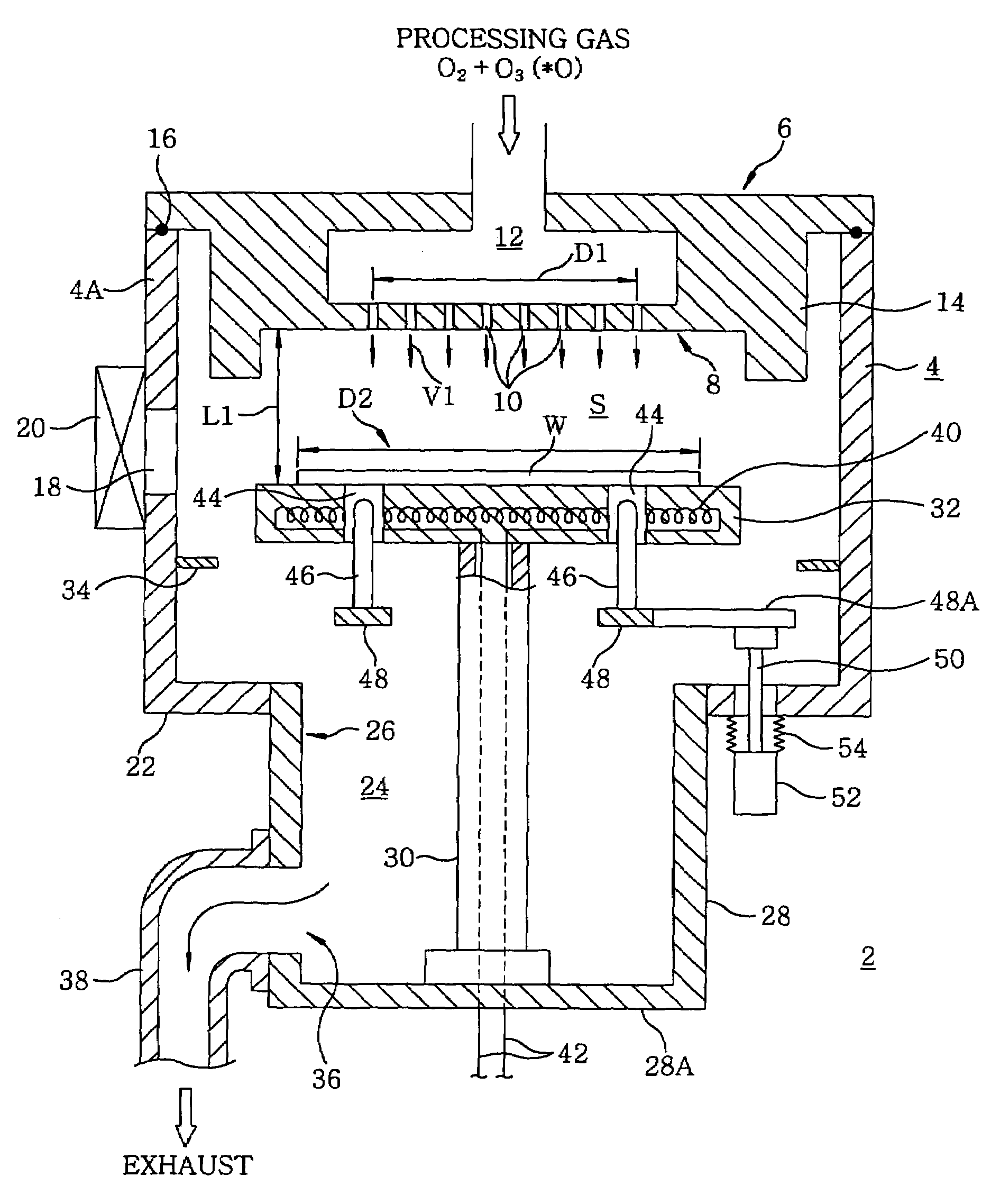
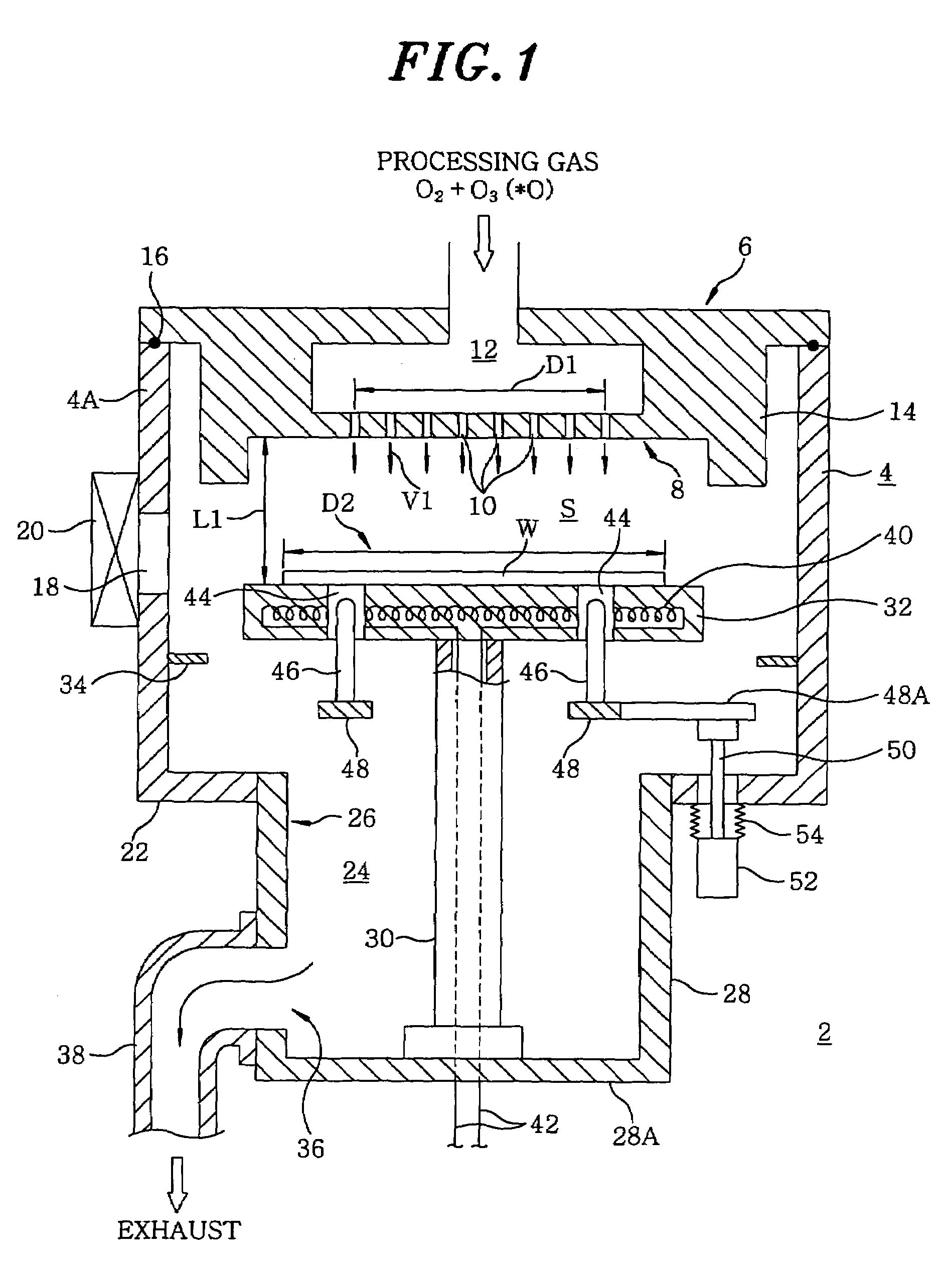
[0030]FIG. 1 shows a cross sectional view of the processing apparatus in accordance with the preferred embodiment of the present invention. FIG. 2 provides a bottom view of a shower head structure shown in FIG. 1. FIG. 3 presents a graph for describing an optimal range of a gas jetting velocity as a function of a head distance. The processing apparatus of this preferred embodiment is the one for reforming tantalum oxide films through an annealing process.

[0031]As shown in FIG. 1, a processing apparatus 2 has a processing chamber 4 made of aluminum and an inside of the processing chamber 4 is approximately of a cylindrical shape. Installed on a ceiling portion of the processing chamber 4 is a shower head structure 6 functioning as a gas supply unit for introducing a required processing gas, e...


PUM

PropertyMeasurementUnit
gas jetting velocityaaaaaaaaaa

Abstract

A processing device, comprising a processing container, a shower head structure provided at the ceiling part of the processing container and having a plurality of gas jetting holes for jetting specified processing gas into the processing container formed in the gas jetting surface thereof facing the inside of the processing container, and a placing stand disposed in the processing container so as to face the shower head structure, wherein a head distance between the gas jetting surface and the placing stand and the blowing speed of gas from the gas jetting holes are set within the range surrounded by connecting, in a square shape with straight lines in a plane coordinate system having the head distance plotted on an abscissa and the gas jetting speed plotted on a coordinate, a point where the blowing speed of the gas from the gas jetting holes at the head distance of 15 mm is 32 m / sec, a point where the blowing speed of the gas from the gas jetting holes at the head distance of 15 mm is 67 m / sec, a point where the blowing speed of the gas from the gas jetting holes at the head distance of 77 mm is 40 m / sec, and a point where the blowing speed of the gas from the gas jetting holes at the head distance of 77 mm is 113 m / sec.

Description

FIELD OF THE INVENTION[0001]The present invention relates to a processing apparatus and a processing method for processing an object to be processed such as a semiconductor wafer.BACKGROUND OF THE INVENTION[0002]In the course of manufacturing a semiconductor integrated circuit (IC), various single wafer processes such as a film forming process, an etching process, a heat treating process, a reforming process and a crystallization process are repeatedly carried out on an object to be processed, e.g., a semiconductor wafer. While executing such processes, processing gases needed for the corresponding processes, e.g., a film formation gas for the film forming process; ozone gas or the like for the reforming process; O2 gas, an inert gas such as N2 gas, or the like for the crystallization process, are respectively introduced into processing chambers.[0003]For instance, in a single wafer processing apparatus for one by one heat treatment on semiconductor wafers, a mounting table incorpor...

Claims


Application Information

Patent Timeline
Patent Type & Authority Patents(United States)
IPC IPC(8): C23C16/00C23C16/06H01L21/31C23C16/44C23C16/455H01L21/00H01L21/316
CPCC23C16/455C23C16/45502C23C16/45565H01L21/02183H01L21/67017H01L21/02255H01L21/02337H01L21/31662H01L21/31683H01L21/02238
Inventor KAKIMOTO, AKINOBUOSHIMO, KENTAROMATSUDO, MASAHIKO
Owner TOKYO ELECTRON LTD
Why Eureka
Try Eureka