Integrated antenna type circuit apparatus

a technology of integrated antennas and circuit devices, which is applied in the direction of basic electric elements, electrical apparatus construction details, and incorporation of printed electric components, etc., can solve the problems of difficult integration of semiconductor circuits to be used inside, difficult to sophisticate antenna performance, and difficult to integrate semiconductor chips and chip parts with other semiconductor chips and chip parts, etc., to reduce the area of antenna conductors, improve emission efficiency, and suppress the effect of increasing the packaging area

Inactive Publication Date: 2009-11-10
SANYO ELECTRIC CO LTD
View PDF26 Cites 42 Cited by
  • Summary
  • Abstract
  • Description
  • Claims
  • Application Information

AI Technical Summary

Benefits of technology

[0010]The present invention has been achieved in view of the foregoing problems. It is thus an object of the present invention to provide an integrated antenna type circuit apparatus which provides excellent circuit characteristics while suppressing an increase in packaging area.
[0013]According to this aspect, the signal processing circuit unit having the circuit device embedded therein and the antenna are laminated with each other. It is therefore possible to integrate the antenna and the signal processing circuit unit without increasing the packaging area. Since the ground conductor is arranged between the antenna and the circuit device of the signal processing circuit unit, it is possible to improve the characteristics of the antenna and suppress malfunctions of the radio frequency circuit ascribable to the emitted electromagnetic waves. In addition, the ground conductor functions as a shield for blocking not only the electromagnetic waves emitted from the antenna but also foreign noise coming from the surroundings. This consequently allows an improvement of the circuit characteristics. Moreover, the ground conductor provides the effect of blocking unnecessary outgoing radiation from the radio frequency circuit, and thus is effective for electromagnetic interference (EMI) control.
[0014]The antenna conductor may be formed on a side of the radio frequency circuit opposite to one from which an external lead electrode is extended. An additional circuit device may be mounted on the side on which the antenna conductor is formed. Mounting the circuit device on a portion of the radio frequency circuit adjacent to the antenna conductor allows a further reduction in area.
[0016]The insulator layer between the antenna conductor and the wiring conductor layer on which the ground conductor is formed may be made of an epoxy or phenol resin. When the material of the insulator layer between the antenna conductor and the ground conductor has a high dielectric constant, it is possible to reduce the area of the antenna conductor, and by extension to miniaturize the integrated antenna type circuit apparatus.
[0017]The insulator layer between the antenna conductor and the wiring conductor layer on which the ground conductor is formed may be made of a fluorocarbon resin or a liquid crystal polymer. The fluorocarbon resin refers to a fluorocarbon polymer which consists of fluorine atoms and carbon atoms. Among the known examples thereof is Teflon (registered trademark). When the material of the insulator layer between the antenna conductor and the ground conductor has a low dielectric constant, it is possible to improve the emission efficiency.
[0018]The circuit device may be a radio frequency identification (RFID) chip. The antenna conductor may receive a carrier transmitted from a reader-writer, and emit a carrier transmitted from the circuit device. This can suppress an increase in the packaging area since the RFID chip and the antenna conductor are laminated with each other. In addition, the ground conductor interposed between the RFID chip and the antenna conductor can improve the antenna characteristics and block foreign noise from the surroundings. Consequently, there is provided an integrated antenna type RFID which has excellent circuit characteristics.

Problems solved by technology

For example, in mobile communication terminals for transmitting and receiving radio frequency signals in the form of electromagnetic waves, including cellular phones, Personal Handyphone Systems, and wireless cards, the miniaturization and integration of the semiconductor circuits to be used inside are significant challenges.
This has made it difficult, however, for these components to be merged with other semiconductor chips and chip parts.
Since the proximity of the antenna and the electronic parts causes limitations on the design pattern, there has been the problem that the antenna is hard to sophisticate in performance.

Method used


Image

  • Integrated antenna type circuit apparatus
  • Integrated antenna type circuit apparatus
  • Integrated antenna type circuit apparatus

Examples


first embodiment

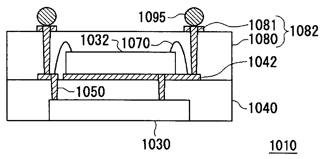
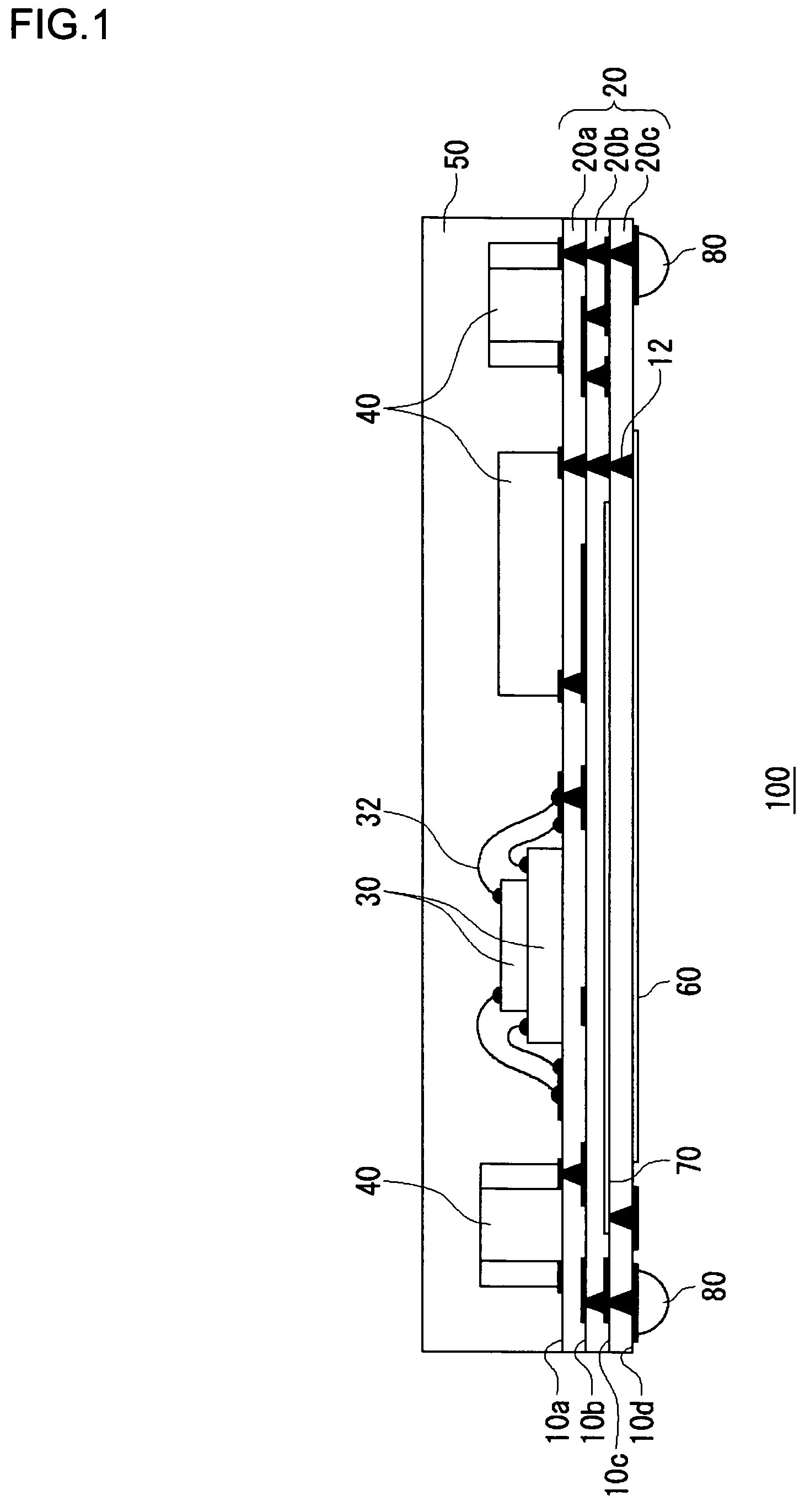
[0045]FIG. 1 is a sectional view of an integrated antenna type circuit apparatus 100 according to a first embodiment. The integrated antenna type circuit apparatus 100 includes an insulating base 20, semiconductor circuit devices 30, chip parts 40, a molding resin 50, an antenna conductor 60, a ground conductor 70, and external lead electrodes 80. For the sake of convenience, in FIG. 1, the side on which the chip parts 40 are mounted shall be referred to as being upward, and the side on which the external lead electrodes 80 are formed being downward.

[0046]An example of the semiconductor circuit devices 30 is an IC chip in which transistors, diodes, and passive elements are integrated. The semiconductor circuit devices 30 are formed on a semiconductor substrate made of silicon, silicon germanium, gallium arsenide, or the like. By such means as a silver paste, the semiconductor circuit devices 30 are die bonded to the insulating base 20 for physical connection. Electrode pads of the s...

second embodiment

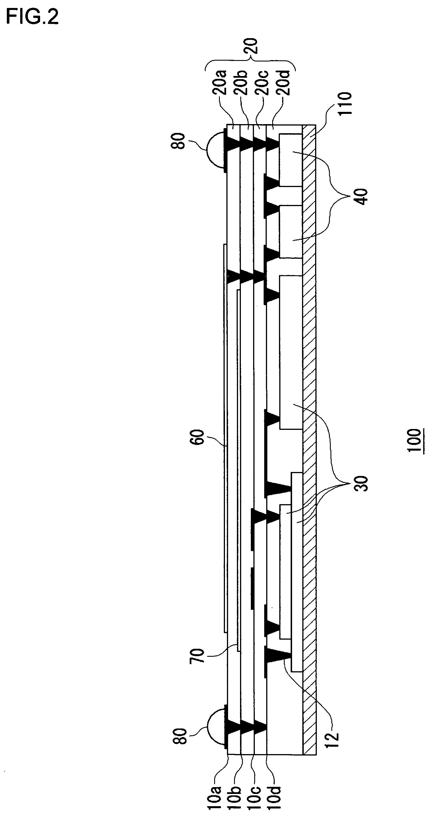
[0074]In the first embodiment, the components of the radio frequency circuit, i.e., the semiconductor circuit devices 30 and the plurality of chip parts 40 are formed on the insulating base 20 and sealed by the molding resin 50 so as to be embedded in the insulator layer.

[0075]In the integrated antenna type circuit apparatuses 100 according to second and subsequent embodiments to be described below, the semiconductor circuit devices 30 and the plurality of chip parts 40 are embedded in the insulating base 20. In the following embodiments, description of the same configuration as in the first embodiment will be omitted as appropriate.

[0076]FIG. 2 is a sectional view showing the configuration of the integrated antenna type circuit apparatus 100 according to the second embodiment. For ease of explanation, the side on which the chip components 40 are mounted shall be referred to as being upward, and the side on which the external lead electrodes 80 are formed being downward.

[0077]The in...

third embodiment

[0089]FIG. 3 is a sectional view showing the configuration of the integrated antenna type circuit apparatus 100 according to a third embodiment. In the integrated antenna type circuit apparatus 100 shown in FIG. 2, the external lead electrodes 80 and the antenna conductor 60 are formed on the same side. In the present embodiment, the antenna conductor 60 is arranged on a side different from the external lead electrodes 80 are.

[0090]In other words, the present embodiment differs from the second embodiment in that the base 110 is also provided with via plugs 12 so as to establish connection between the external lead electrodes 80 and the wiring conductors. In other respects, the structure is the same as in the second embodiment.

[0091]In addition to the effects of the second embodiment described above, the present embodiment provides the following effects.

[0092]Since the antenna conductor 60 and the external lead electrodes 80 are formed on the opposite sides, the antenna falls on the ...


PUM


Abstract

An integrated antenna type circuit apparatus which provides excellent circuit characteristics while suppressing an increase in packaging area. The integrated antenna type circuit apparatus includes an insulating base, a semiconductor circuit device, chip parts, a molding resin, an antenna conductor, a ground conductor, and external lead electrodes. The plurality of chip parts are mounted on the insulating base, and are soldered to electrodes of wiring conductors on the top of the insulating base for electric and physical connection. The insulating base has a multilayer structure, being formed by laminating a plurality of insulator layers. The antenna conductor is formed on the bottom of the insulating base. A wiring conductor adjacent to the antenna conductor is provided with the ground conductor so that it overlaps with the antenna conductor.

Description

BACKGROUND OF THE INVENTION[0001]1. Field of the Invention[0002]The invention relates to a radio frequency semiconductor circuit apparatus with an integrated antenna.[0003]2. Description of the Related Art[0004]While compact information terminals such as a cellular phone and a personal digital assistance (PDA) are getting sophisticated at increasing speed, miniaturization and weight saving are indispensable for these products to be accepted in the market. On this account, not only functional and performance sophistication but also miniaturization is even required of the semiconductor circuits to be used in these compact information terminals.[0005]For example, in mobile communication terminals for transmitting and receiving radio frequency signals in the form of electromagnetic waves, including cellular phones, Personal Handyphone Systems, and wireless cards, the miniaturization and integration of the semiconductor circuits to be used inside are significant challenges. These mobile ...

Claims


Application Information

Patent Timeline
Patent Type & Authority Patents(United States)
IPC IPC(8): H01L23/02
CPCH01Q1/22H01Q1/2283H01L24/24H01L2224/12105H05K1/0298H05K1/16H01L2924/01079H01L2224/45144H01L2924/3011H01L2924/18162H01L2924/15311H01L2224/73267H01L2224/32145H01L2224/24195H01L2224/24145H01L2224/24137H01L2224/48091H01L2224/48227H01L2224/48464H01L2924/19105H01L24/45H01L2225/06568H01L2924/30107H01L2924/3025H01L2924/00H01L2924/00014H01L2924/181H01L2924/14H01L2223/6677H01L2224/05573H01L2224/05568H01L2224/05001H01L2224/04105H01L2224/32225H01L2224/0554H01L24/19H01L2224/05599H01L2224/05099H01L2924/00012H01L2224/0555H01L2224/0556
Inventor SAKAI, ATSUSHIUSUI, RYOSUKEINOUE, YASUNORI
Owner SANYO ELECTRIC CO LTD
Why Eureka
Try Eureka