Power module

Active Publication Date: 2017-04-11
DELTA ELECTRONICS SHANGHAI CO LTD
View PDF4 Cites 0 Cited by
  • Summary
  • Abstract
  • Description
  • Claims
  • Application Information

AI Technical Summary

Benefits of technology

[0008]The present invention provides a power module. The magnetic assembly and the switching device are integrated at the same time, so that the power module with high efficiency and hi

Problems solved by technology

Consequently, the ratio of occupied space and the power loss are increased.
Although both of them are optimized t

Method used


Image

  • Power module
  • Power module
  • Power module

Examples


first embodiment

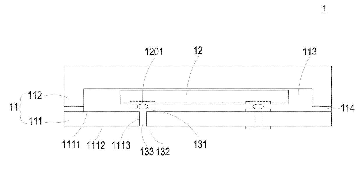
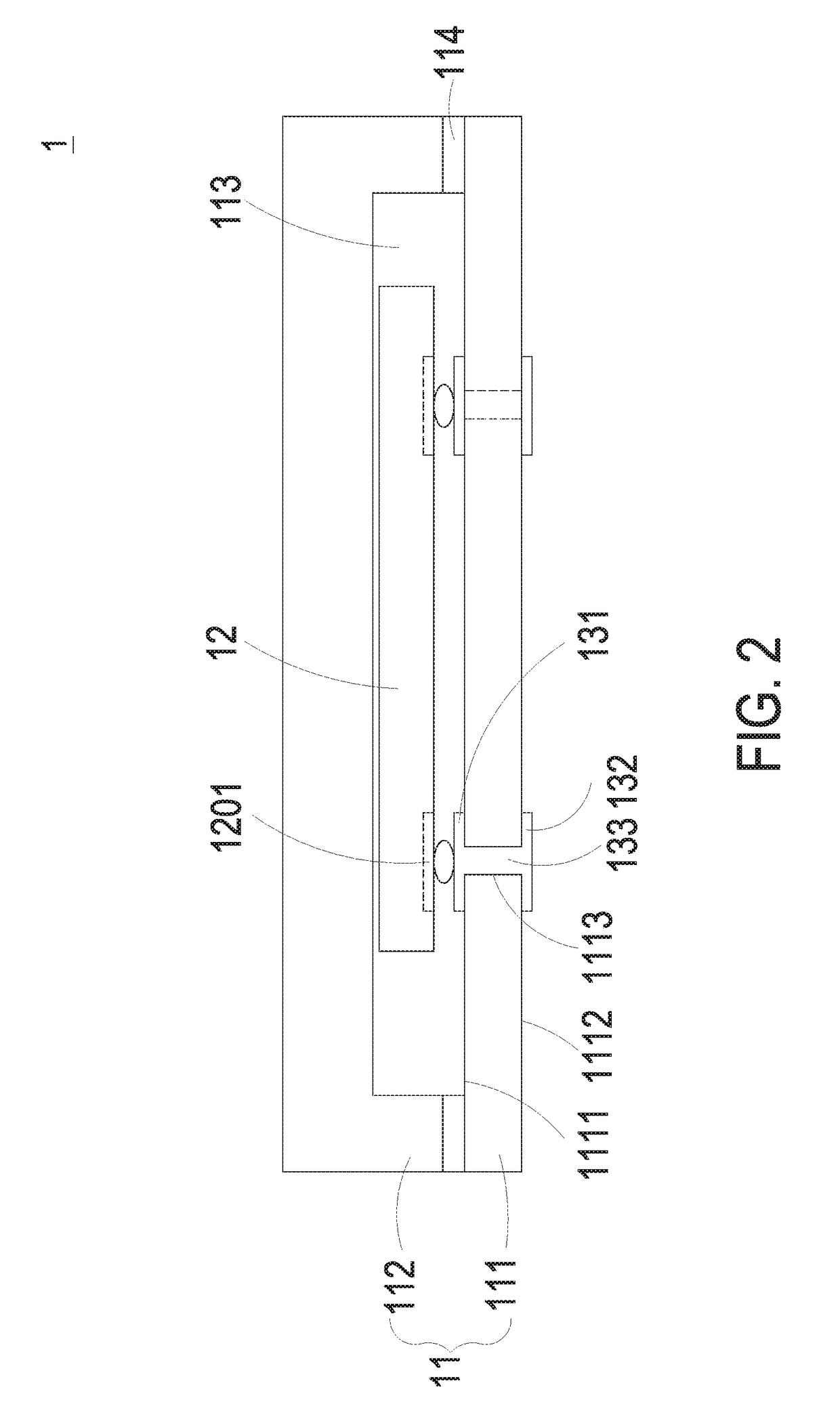
[0032]FIG. 2 is a schematic cross-sectional view illustrating a power module according to the present invention. As shown in FIG. 2, the power module 1 includes a magnetic assembly 11, a switching device 12, a first upper conductive element 131, a first lower conductive element 132 and a first sidewall conductive element 133. In the embodiment, the magnetic assembly 11 includes a first magnetic core 111, a second magnetic core 112 and a receiving space 113. The first magnetic core 111 and the second magnetic core 112 are assembled with each other via an adhesive material 114 so as to form the magnetic assembly 11. Accordingly, the property, such as the inductance value, of the magnetic assembly 11 is adjustable by means of adjusting the thickness of the adhesive material 114, so as to create more variety of the design modification. The first magnetic core 111 includes a first top surface 1111, a first bottom surface 1112 and at least one sidewall through-hole 1113. The second magnet...

second embodiment

[0037]FIG. 5 is a schematic cross-sectional view illustrating a power module according to the present invention. In the embodiment, the structures, elements and functions of the power module 1a are similar to those of the power module 1 in FIG. 2, and are not redundantly described herein. Different from the power module 1 of FIG. 2, the power module 1a further includes a first series winding 14 and a second series winding 15 disposed on the first magnetic core 111 and the second magnetic core 112, respectively. The first series winding 14 includes a first upper winding set 141, a first lower winding set 142 and a first sidewall winding set 143. The first upper winding set 141 is disposed on the first top surface 1111 of the first magnetic core 111. The first lower winding set 142 is disposed on the first bottom surface 1112 of the first magnetic core 111. The first sidewall winding set 143 is disposed in the first sidewall through-holes 1113 located at two opposite sidewalls of the ...

third embodiment

[0038]FIG. 6 is a schematic cross-sectional view illustrating a power module according to the present invention. In the embodiment, the structures, elements and functions of the power module 1b are similar to those of the power module 1a in FIG. 5, and are not redundantly described herein. Comparing with the power module 1a of FIG. 5, the power module 1b further includes an insulating dielectric layer 17 and a conductive layer 18. The insulating dielectric layer 17 is disposed on the first upper conductive element 131 and the first upper winding set 141 of the first series winding 14, and partially exposes the first upper conductive element 131 and the first upper winding set 141 of the first series winding 14 by means of drilling, so that a conductive blind via 181 can be constructed on the insulating dielectric layer 17 and electrically connected between the conductive layer 18 and the first upper conductive element 131 or between the conductive layer 18 and the first upper windin...


PUM


Abstract

A power module is disclosed. The power module includes a magnetic assembly, a switching device, a first upper conductive element and a first sidewall conductive element. The magnetic assembly has a first magnetic core, a second magnetic core and a receiving space. The first magnetic core has a first top surface, a first bottom surface and at least one first sidewall through-hole. The second magnetic core is coupled with the first magnetic core. The receiving space is formed between the first magnetic core and the second magnetic core. The switching device is disposed on the first top surface and accommodated in the receiving space. The first upper conductive element is disposed on the first top surface of the first magnetic core and electrically connected to the switch component. The first sidewall conductive element is disposed in the first sidewall through-hole and electrically connected to the first upper conductive element.

Description

FIELD OF THE INVENTION[0001]The present invention relates to a power module, and more particularly to a powder module having an integrated magnetic assembly.BACKGROUND OF THE INVENTION[0002]With the increasing requests of human intelligent life, the increasing requirements of developing intelligent products, and the growing of Internet of Things (IoT), the requirements of data transmission and processing are increasing day by day. In a centralized data processing center, servers are regarded as key elements and have motherboards including CPU, chipsets, memories, and equivalent digital chips for data processing with power supplies and necessary peripheral elements. For increasing the processing capacity of servers in a unit volume, the number of digital chips and the density of integration are increased correspondingly. Consequently, the ratio of occupied space and the power loss are increased. Therefore, the power supply (also called as motherboard power due to that the power suppl...

Claims


Application Information

Patent Timeline
IPC IPC(8): H01L29/00H02M7/00H01L49/02H01L23/522H01L23/31
CPCH01L23/5227H01L28/10H02M7/003H01L23/31H01F3/10H02M1/00H02M1/0064H01L23/055H02M3/158H01L2224/48227H01L2924/16152H01L2924/181H01L2224/48091H01L24/19H01L2224/16227H01L2224/16235H01L2224/73267H01L2924/19105H01L2224/48235H01L24/16H01L24/48Y02B70/10H01L2924/00012H01L2924/00014
Inventor ZENG, JIANHONGHONG, SHOUYUZHOU, MIN
Owner DELTA ELECTRONICS SHANGHAI CO LTD
Why Eureka
Try Eureka