High frequency surface acoustic wave device

Inactive Publication Date: 2009-11-10
TATUNG UNIVERSITY +1
View PDF5 Cites 6 Cited by
  • Summary
  • Abstract
  • Description
  • Claims
  • Application Information

AI Technical Summary

Benefits of technology

[0009]The object of the present invention is to provide a high frequency surface acoustic wave device, which may be manufact

Problems solved by technology

However, the contact-type lithography apparatus cannot be used in the manufacturing process with such high resolution.
Instead, a stepper and an expensive dry-etching process must be used to manufacture such a high frequency surface acoustic wave device on the lithium niobate substrate.
As a result, the cost of the manufacturing process is increased dramatically and not favorable for massive production process.
However, the roughness of the diamond film of the surface acoustic wave device manufactured by the above process is not suitable for the transmission of the surface acoustic wave.
In other words, the proposed manufacturing process has lots of drawbacks, suc

Method used


Image

  • High frequency surface acoustic wave device
  • High frequency surface acoustic wave device
  • High frequency surface acoustic wave device

Examples


first embodiment

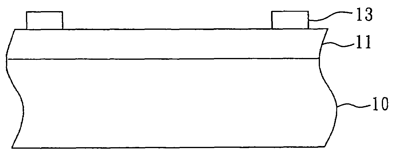
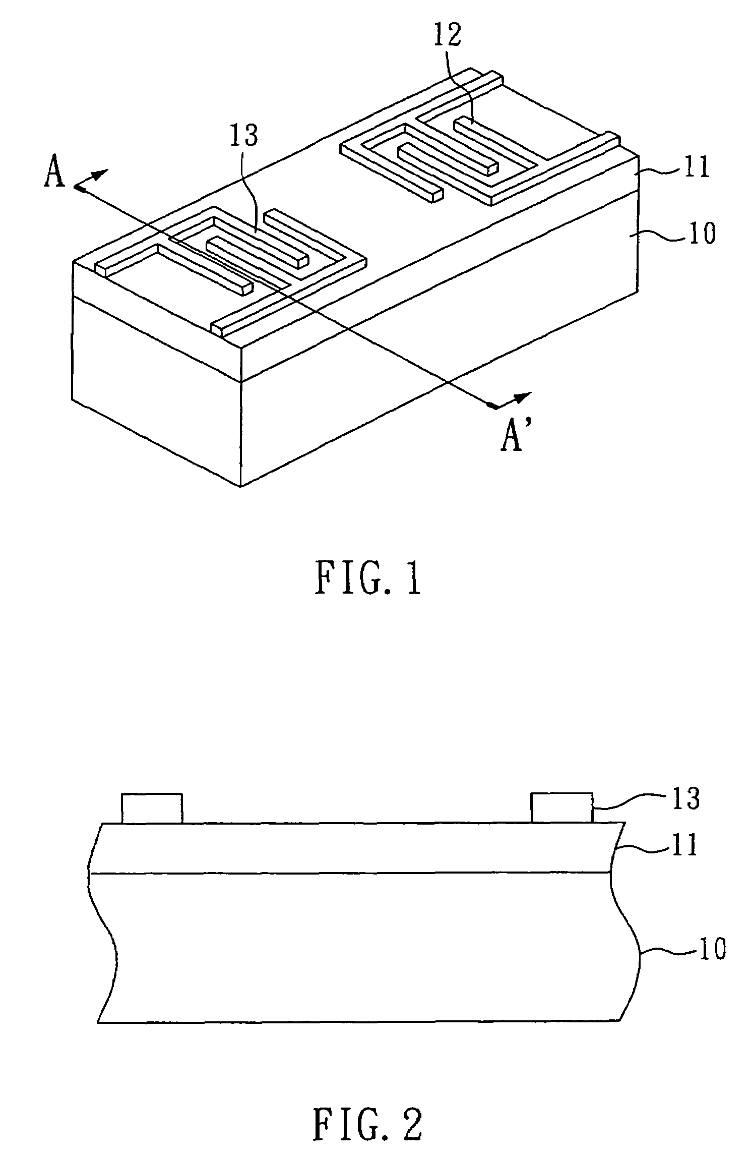
[0022]As shown in FIG. 1 and FIG. 2, the high frequency surface acoustic wave device according to the first embodiment of the present invention comprises a piezoelectric substrate 10, a high acoustic velocity layer 11, an input transducing part 12, and an output transducing part 13, wherein the acoustic velocity of the surface acoustic wave of the high acoustic velocity layer 11 is larger than 5000 m / sec. In the present embodiment, the high acoustic velocity layer 11 is made of aluminum oxide and formed on the surface of the piezoelectric substrate 10. On the other hand, the input transducing part 12 and the output transducing part 13 are each an interdigital transducer. Both of the input transducing part 12 and the output transducing part 13 are made of aluminum. The interdigital transducers are formed on the surface of the high acoustic velocity layer 11, and the line width of the interdigital transducers is between 0.5 μm and 5 μm.

[0023]The manufacturing process of the high frequ...

second embodiment

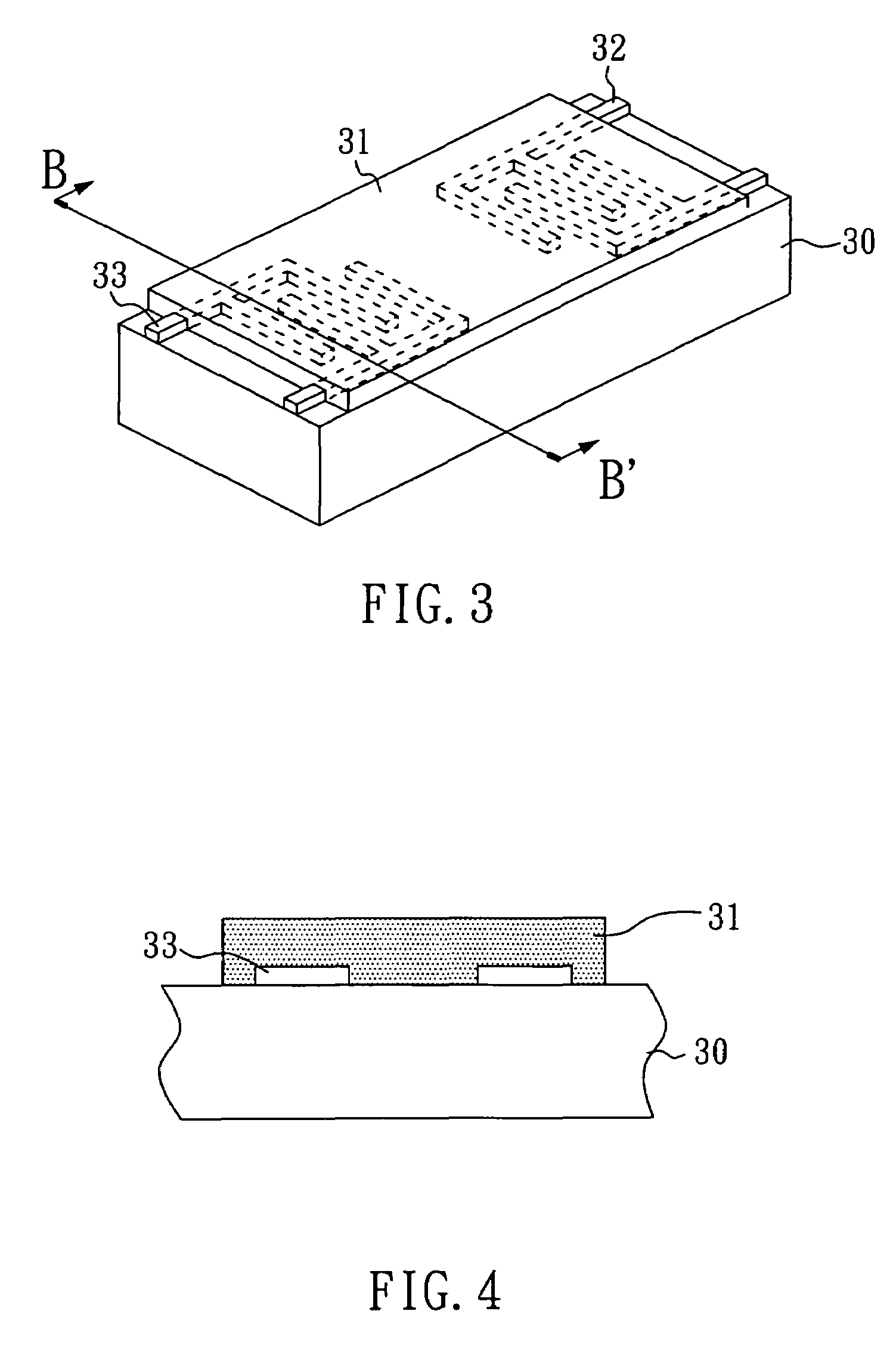
[0030]As shown in FIG. 3 and FIG. 4, the high frequency surface acoustic wave device according to the second embodiment of the present invention has a structure similar to that of the high frequency surface acoustic wave device according to the first embodiment of the present invention. The high frequency surface acoustic wave device according to the second embodiment of the present invention comprises a piezoelectric substrate 30, a high acoustic velocity layer 31, an input transducing part 32, and an output transducing part 33. However, in the present embodiment, the input transducing part 32 and the output transducing part 33, i.e. the interdigital transducers, are formed on the piezoelectric substrate 30. Besides, the high acoustic velocity layer 31 is formed on the input transducing part 32, the output transducing part 33, and the surface of the piezoelectric substrate 31 located between the input transducing part 32 and the output transducing part 33. Moreover, the line width ...


PUM


Abstract

The present invention relates to a high frequency surface acoustic wave device, which may be manufactured by the same manufacturing equipment, and with the same material, as those required for manufacturing a low frequency surface acoustic wave device. The disclosed high frequency surface acoustic wave device comprises: a piezoelectric substrate; a high acoustic velocity layer formed on the surface of the piezoelectric substrate whose acoustic velocity of the surface acoustic wave is larger than 5000 m/sec; an input transducing part; and an output transducing part; wherein the input transducing part and the output transducing part are formed in pair on or below the surface of the high acoustic velocity layer. Besides, the high acoustic velocity layer is preferably made of aluminum oxide, and formed on the surface of the piezoelectric substrate by an electron-beam evaporation process. The thickness thereof is preferably between 2 μm and 20 μm.

Description

BACKGROUND OF THE INVENTION[0001]1. Field of the Invention[0002]The present invention relates to a high frequency surface acoustic wave device and, more particularly, to a high frequency surface acoustic wave device which may be manufactured by the same manufacturing equipment, and with the same material, as those required for manufacturing a low frequency surface acoustic wave device.[0003]2. Description of Related Art[0004]The surface acoustic wave device has been widely used as the middle-frequency filter of a TV. Besides, as the improvement in the material technology, the surface acoustic wave device can be used as a filter in the mobile communication field. Moreover, since the surface acoustic wave device has certain characteristics such as low loss level, high attenuation, small-size, and light-weight, the surface acoustic wave device is applied widely in the wireless communication field.[0005]Since the surface acoustic wave device is widely applied in the communication produc...

Claims


Application Information

Patent Timeline
IPC IPC(8): H01L41/08
CPCH03H9/02574
Inventor SHIH, WEN-CHINGHUANG, RUI-CHENG
Owner TATUNG UNIVERSITY
Why Eureka
Try Eureka