Electro-optical device, and projector and electronic apparatus including the same
a technology of optical devices and electronic equipment, applied in the field of optical devices, can solve the problems of deterioration of flicker characteristics of display surfaces, uneven image quality, and reduction of contrast ratio, and achieve the effect of ensuring high-quality images
- Summary
- Abstract
- Description
- Claims
- Application Information
AI Technical Summary
Benefits of technology
Problems solved by technology
Method used
Image
Examples
first embodiment
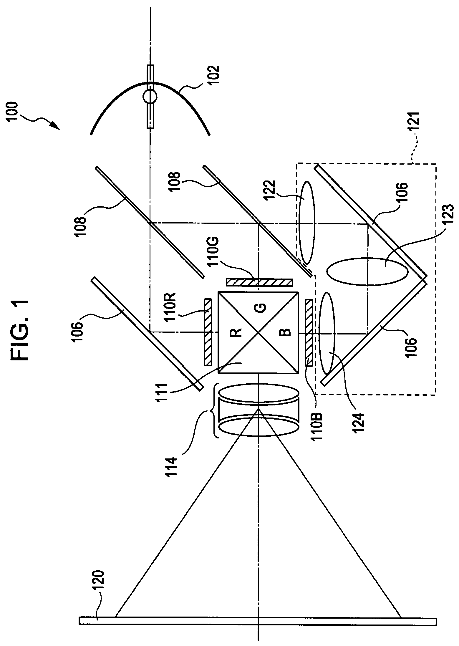
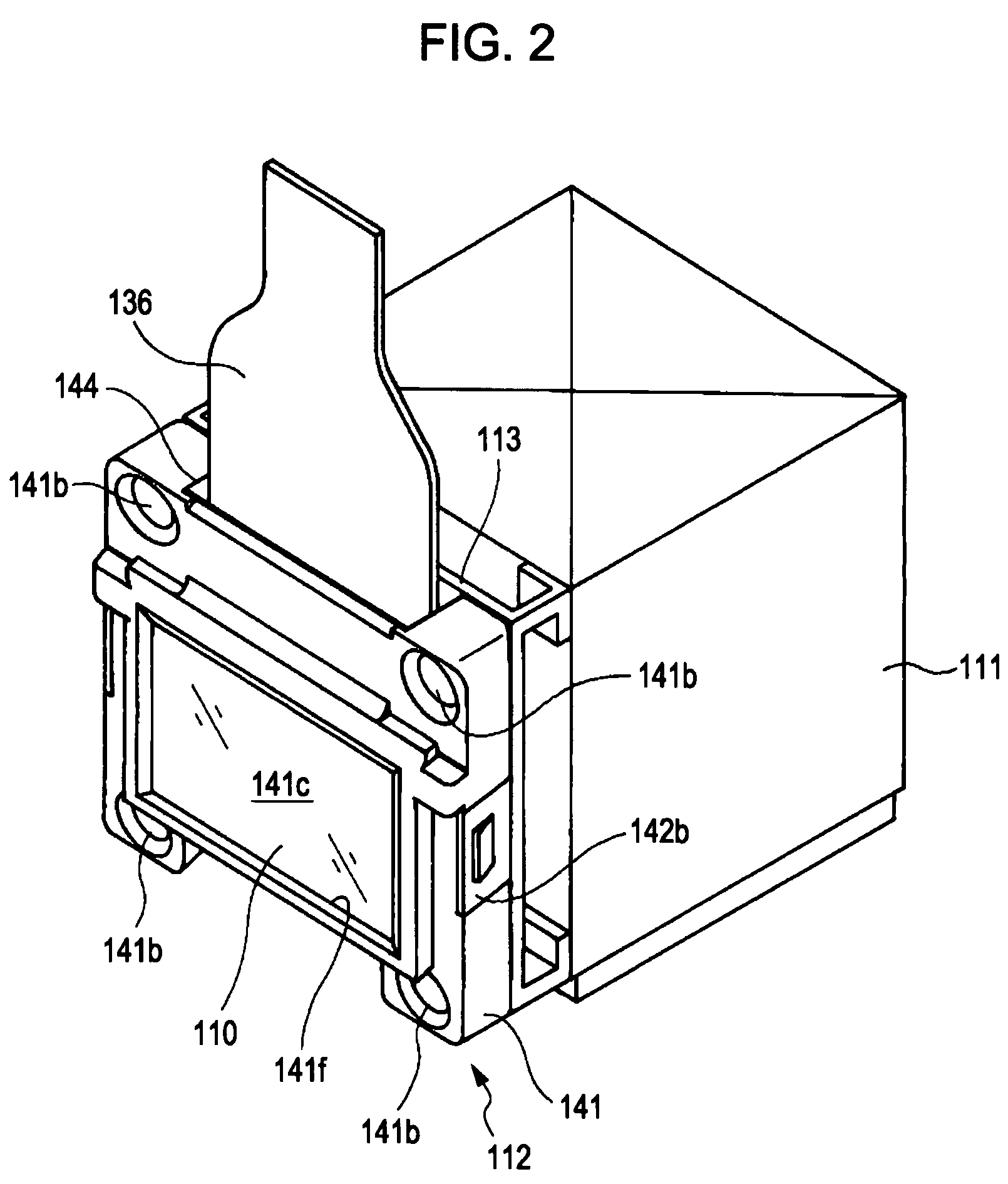
[0045]Embodiments of the invention will be described with reference to the drawings. FIGS. 1 to 9 show the invention. FIG. 1 is a schematic diagram of a color liquid crystal projector. FIG. 2 is a perspective view of a holder that holds a liquid crystal light valve, the holder being attached to a dichroic prism. FIG. 3 is an exploded perspective view of the holder and the liquid crystal light valve.
[0046]As shown in FIG. 1, a color liquid crystal projector unit serving as an exemplary electronic apparatus includes a liquid crystal projector 100 and a screen 120. The liquid crystal projector 100 includes three liquid crystal light valves 110R, 110G, and 110B, each having a liquid crystal light valve main unit (light-modulating liquid crystal device) 130 for modulating a light beam of its associated color R, G, or B.
[0047]In the liquid crystal projector 100, when projection light is emitted from a lamp unit 102 having a white light source such as a metal halide lamp or the like, the p...
second embodiment
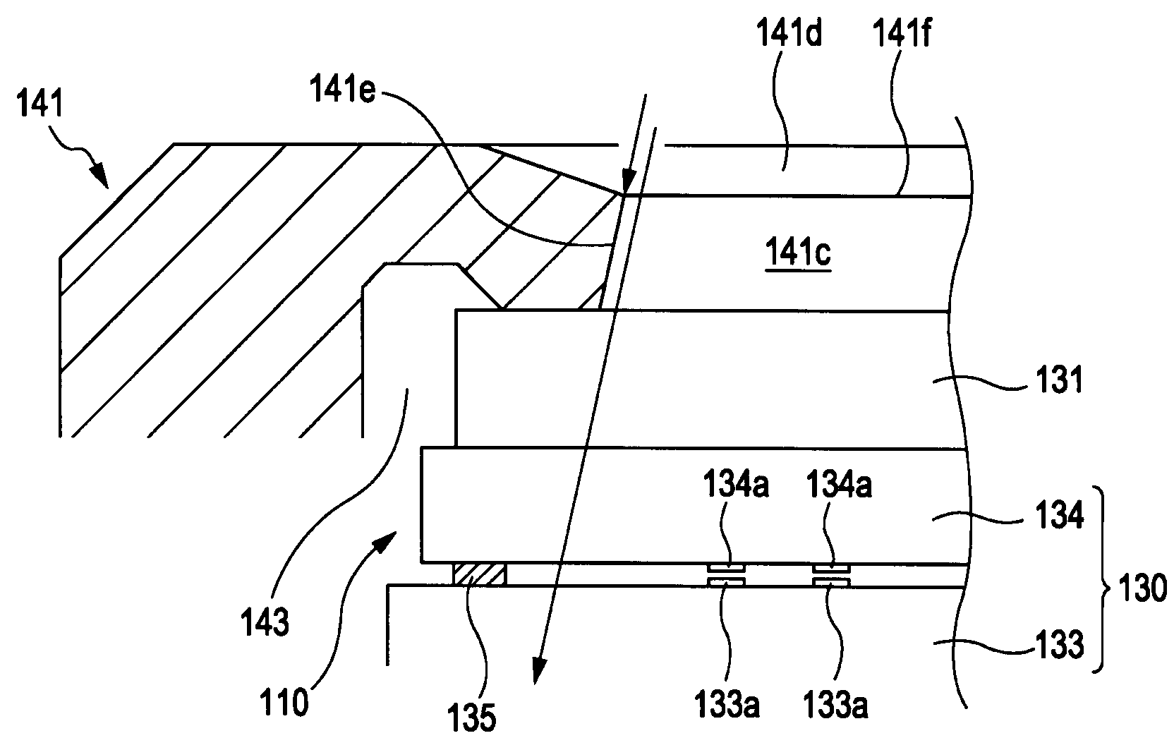
[0077]FIG. 10 is an enlarged cross-sectional view, corresponding to FIG. 6, according to a In FIG. 10, the same reference numerals are used to denote the same blocks as those shown in FIG. 6 to simplify the description.
[0078]In the second embodiment, besides the edge portions 141f, the walls 141e additionally serve as low-reflectivity portions. That is, in the second embodiment, each wall 141e is tapered in the direction extending from the edge portion 141f toward the container 143. As a result, the wall 141e is prevented from being irradiated with diagonal light.
[0079]As has been described above, diagonal light enters at an angle of 10° to 15° with respect to the light projection direction. Thus, when the wall 141e is tapered toward the container 143 at a tilt angle of about 10° to 15°, there will be no diagonal light directed to the wall 141e, and hence no light will be reflected from the wall 141e. As a result, no light is directed to the TFT elements 133a, resulting in a furthe...
third embodiment
[0080]FIG. 11 is an enlarged cross-sectional view, corresponding to FIG. 6, according to a In FIG. 11, the same reference numerals are used to denote the same blocks as those shown in FIG. 6 to simplify the description.
[0081]The third embodiment is a modification of the second embodiment described above. The wall 141e is halfway tapered (the tapered half being toward the edge portion 141f) at a tilt angle greater than the tilt angle (about 10° to 15°) of diagonal light so that the wall 141e extends in the direction from the edge portion 141f toward the container 143, thereby allowing the wall 141e to serve as a low-reflectivity portion. The remaining wall 141e toward the container 143 is a vertical side, as in the first embodiment.
[0082]A line connecting the edge of the vertical side of the wall 141e toward (the emitting side of) the container 143 and the edge portion 141f toward the incident side is tilted at an angle equal to or greater than the tilt angle of the diagonal light. ...
PUM
| Property | Measurement | Unit |
|---|---|---|
| tilt angle | aaaaa | aaaaa |
| scattering angle | aaaaa | aaaaa |
| angle | aaaaa | aaaaa |
Abstract
Description
Claims
Application Information
 - R&D
- Intellectual Property
- Life Sciences
- Materials
- Tech Scout
- Unparalleled Data Quality
- Higher Quality Content
- 60% Fewer Hallucinations
Browse by: Latest US Patents, China's latest patents, Technical Efficacy Thesaurus, Application Domain, Technology Topic, Popular Technical Reports.
© 2025 PatSnap. All rights reserved.Legal|Privacy policy|Modern Slavery Act Transparency Statement|Sitemap|About US| Contact US: help@patsnap.com


