R-T-B based rare earth permanent magnet and method for production thereof
a rare earth permanent magnet and rtb technology, applied in the field of rare earth permanent magnets, can solve the problems of difficult to obtain sufficient coercive force, significant decrease in coercive force along with temperature increase, etc., and achieve high residual magnetic flux density and high coercive force
- Summary
- Abstract
- Description
- Claims
- Application Information
AI Technical Summary
Benefits of technology
Problems solved by technology
Method used
Image

Examples
first example
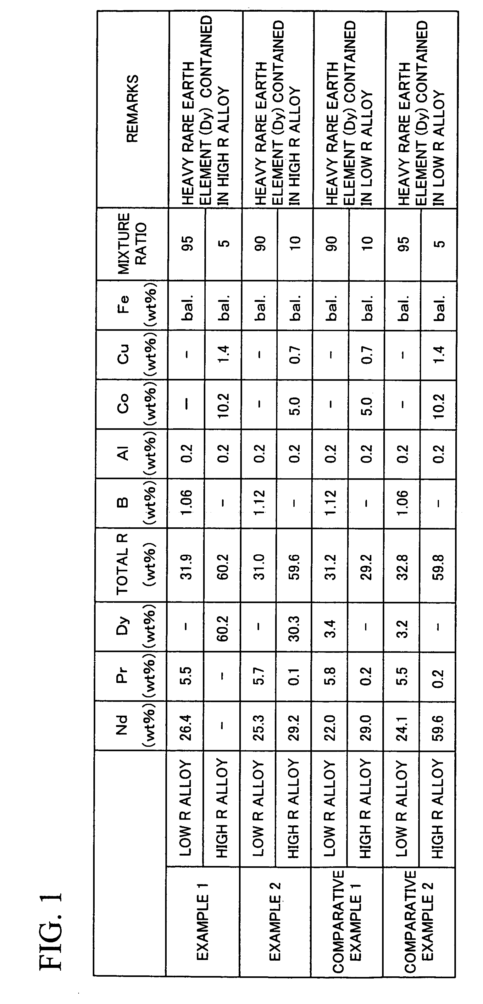
[0080]A low R alloy and a high R alloy were prepared by high frequency dissolution in an Ar atmosphere. The composition of the low R alloy and that of the high R alloy are shown in FIG. 1. In FIG. 1, Dy as a heavy rare earth element was added to the high R alloy in Examples 1 and 2, whereas it was added to the low R alloy in Comparative examples 1 and 2.
[0081]The prepared low R alloy and high R alloy were allowed to absorb hydrogen at room temperature, and are then subjected to a dehydrogenation treatment at 600° C. for 1 hour in an Ar atmosphere.
[0082]After completion of the hydrogen absorption and dehydrogenation treatment, the low R alloy and the high R alloy were crushed by a brown mill in a nitrogen atmosphere. Thereafter, they were pulverized by a jet mill using high-pressure nitrogen gas, so as to obtain pulverized powders with a mean particle size of 3.5 μm. It is to be noted that the low R alloy was mixed with the high R alloy during the crushing, and that 0.05% of oleic am...
second example
[0100]A low R alloy and a high R alloy, which have the same compositions as those in Example 1, were prepared. Sintered magnets were produced in the same processes as those in the first example with the exception that the particle size (mean particle size) of a pulverized powder and the sintering temperature were changed as follows. Regarding the obtained sintered magnets, the same composition analysis and measurement of magnetic properties as those in Example 1 were carried out. The results are shown in FIG. 6.
[0101]Example 1: the particle size of a pulverized powder =3.5 μm, the sintering temperature =1,030° C.
[0102]Example 3: the particle size of a pulverized powder =3.5 μm, the sintering temperature =1,050° C.
[0103]Example 4: the particle size of a pulverized powder =4.5 μm, the sintering temperature =1,030° C.
[0104]Example 5: the particle size of a pulverized powder =4.5 μm, the sintering temperature =1,050° C.
[0105]As shown in FIG. 6, the compositions of the sintered bodies ar...
third example
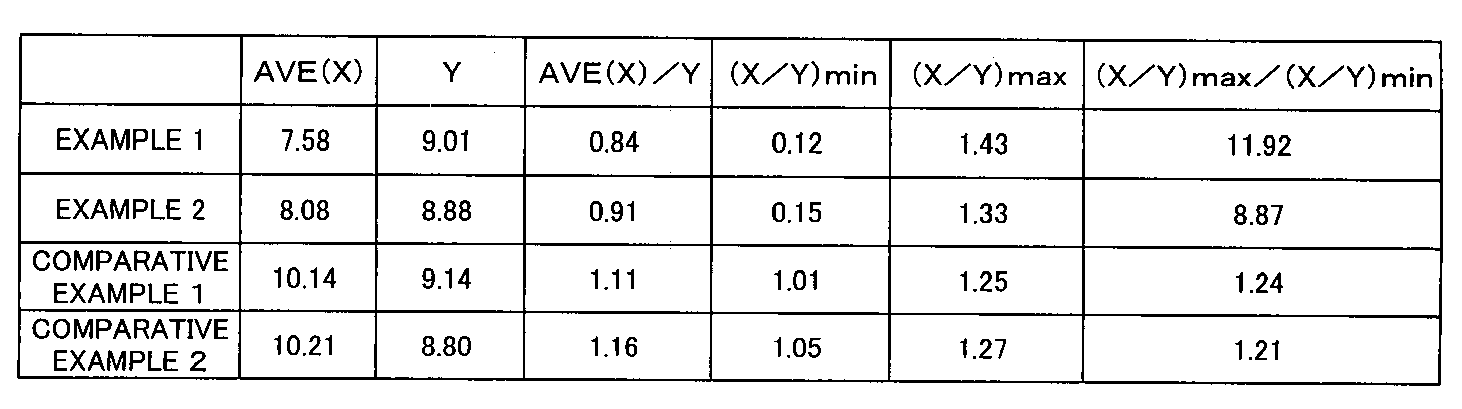
[0112]Sintered magnets were produced in the same processes as those in the first example with the exceptions that low R alloys and high R alloys shown in FIG. 12 were used, that the particle sizes of the pulverized powders were set as described below, and that the sintering temperature was set at 1,070° C. Regarding the obtained sintered magnets, the same measurement and observation as those in the first example were carried out. The chemical compositions of the obtained sintered bodies and the magnetic properties thereof are shown in FIG. 13. The results regarding element mapping are shown in FIG. 14 (Example 6) and FIG. 15 (Comparative example 3). In Example 6, the Dy amount contained in the high R alloy powders was 37 wt % with respect to the Dy amount contained in the sintered body. In Example 7, the Dy amount contained in the high R alloy powders was 52 wt % with respect to the Dy amount contained in the sintered body.
[0113]In addition, the AVE(X), Y, AVE(X) / Y, (X / Y)min, and (X...
PUM
| Property | Measurement | Unit |
|---|---|---|
| grain size | aaaaa | aaaaa |
| grain size | aaaaa | aaaaa |
| weight ratio | aaaaa | aaaaa |
Abstract
Description
Claims
Application Information
 - R&D
- Intellectual Property
- Life Sciences
- Materials
- Tech Scout
- Unparalleled Data Quality
- Higher Quality Content
- 60% Fewer Hallucinations
Browse by: Latest US Patents, China's latest patents, Technical Efficacy Thesaurus, Application Domain, Technology Topic, Popular Technical Reports.
© 2025 PatSnap. All rights reserved.Legal|Privacy policy|Modern Slavery Act Transparency Statement|Sitemap|About US| Contact US: help@patsnap.com