Implantable medical device with improved EMI filter

a medical device and filter technology, applied in the field of implantable medical devices, can solve the problems of affecting the operation of the implanted medical device,

Inactive Publication Date: 2009-11-17
PACESETTER INC
View PDF3 Cites 34 Cited by
  • Summary
  • Abstract
  • Description
  • Claims
  • Application Information

AI Technical Summary

Benefits of technology

[0012]Optionally, the method may include providing, at the filtering stage, an impedance component to attenuate an amplitude characteristic of the EMI signal with respect to frequency. Optionally, the bypassing operation may further include creating a low resistance path for an energy pulse to follow in order to protect a portion of the filtering stage. The bypassing may further include protecting a portion of the filtering stage utilizing a non-linear device that allows passage of the energy pulse. Optionally, the non-linear device may be selected from a group comprising a diode for alternating current (DIAC), a metal oxide semiconductor transistor (MOSFET), an insulated gate field effect transistor (IGFET), a field effect transistor (FET), an insulated gate bipolar transistor (IGBT), and a bipolar transistor.

Problems solved by technology

The EMI signal may then interfere with the operation of the implanted medical device.
For instance, the EMI signal may inhibit pacing or may cause fast, erratic pacing.
In addition, strong EMI signals may cause other problems with the internal electrical circuitry, such as to mistakenly indicate an end-of-battery life, inadvertently reset power-up conditions, cause over-sensing / under-sensing, or cause permanent damage to the circuitry.
However, EMI filters that include a series element are generally useful only within dedicated sensing paths or low voltage delivery paths, such as in pacemakers.
Such EMI filters are not practical for use in high energy delivery paths, for example, as in defibrillators.
Further, EMI filters that include a resistor or lossy inductor may be unable to withstand the high current and or high voltage present in a high-energy delivery path.

Method used


Image

  • Implantable medical device with improved EMI filter
  • Implantable medical device with improved EMI filter
  • Implantable medical device with improved EMI filter

Examples


Embodiment Construction

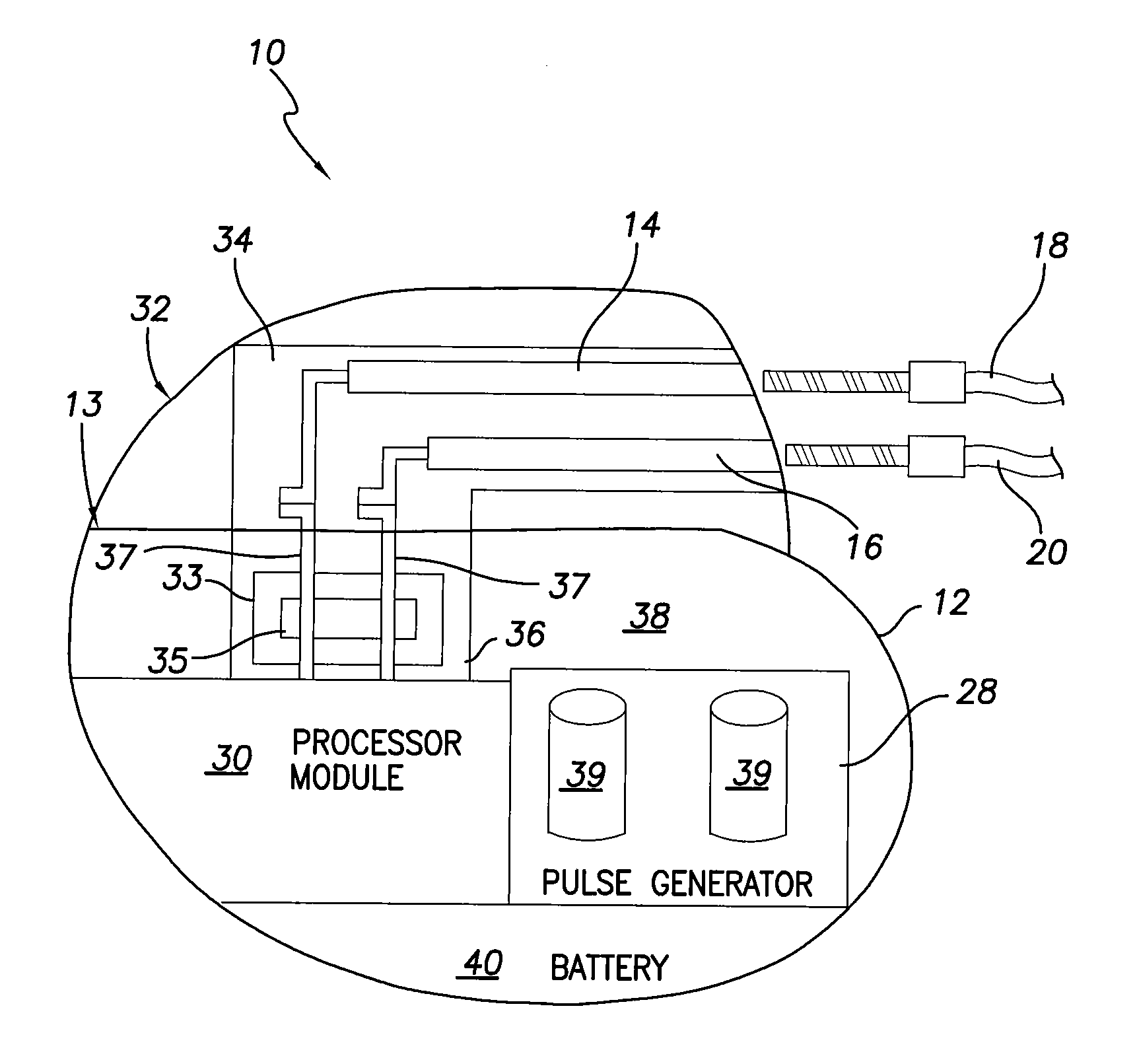
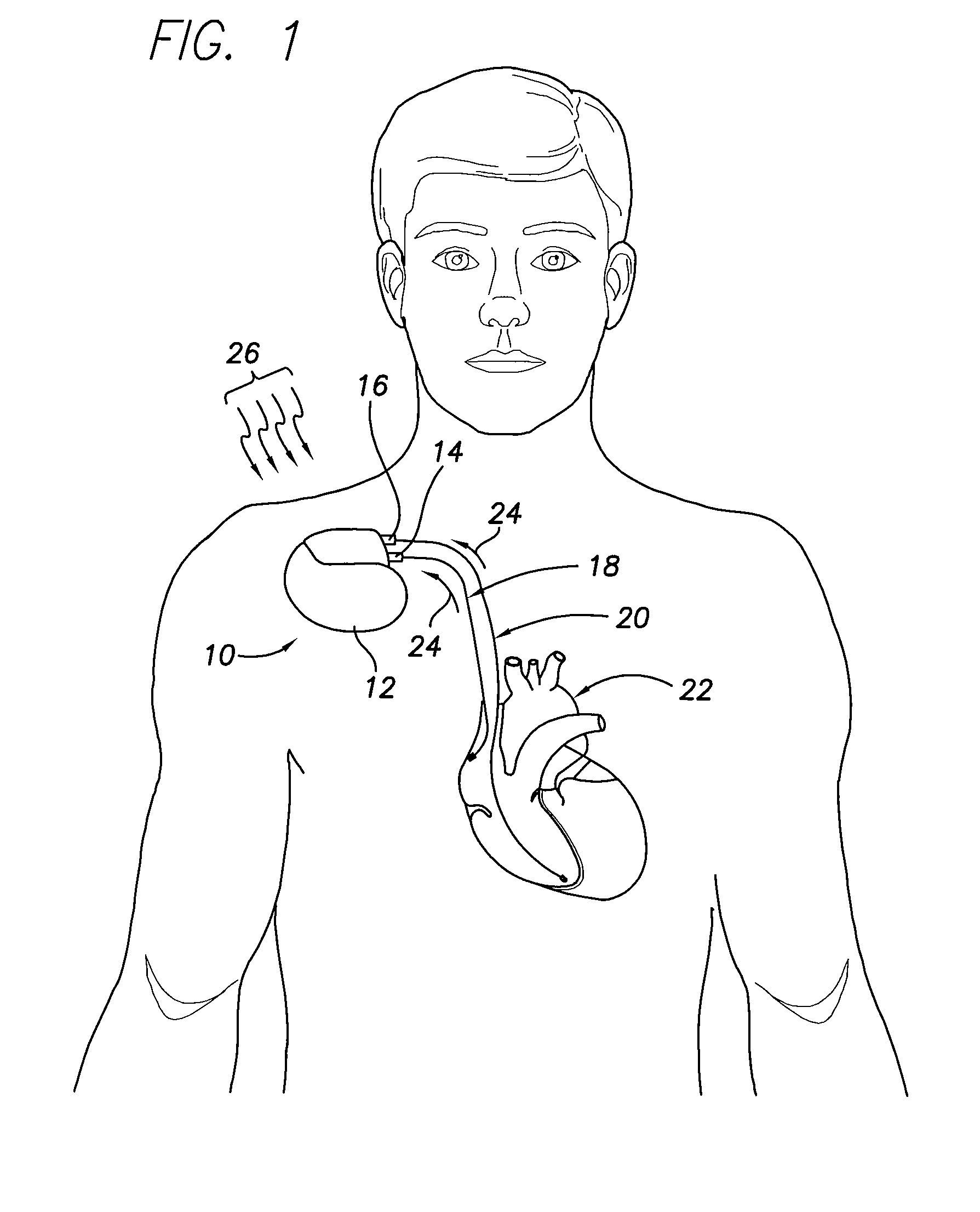
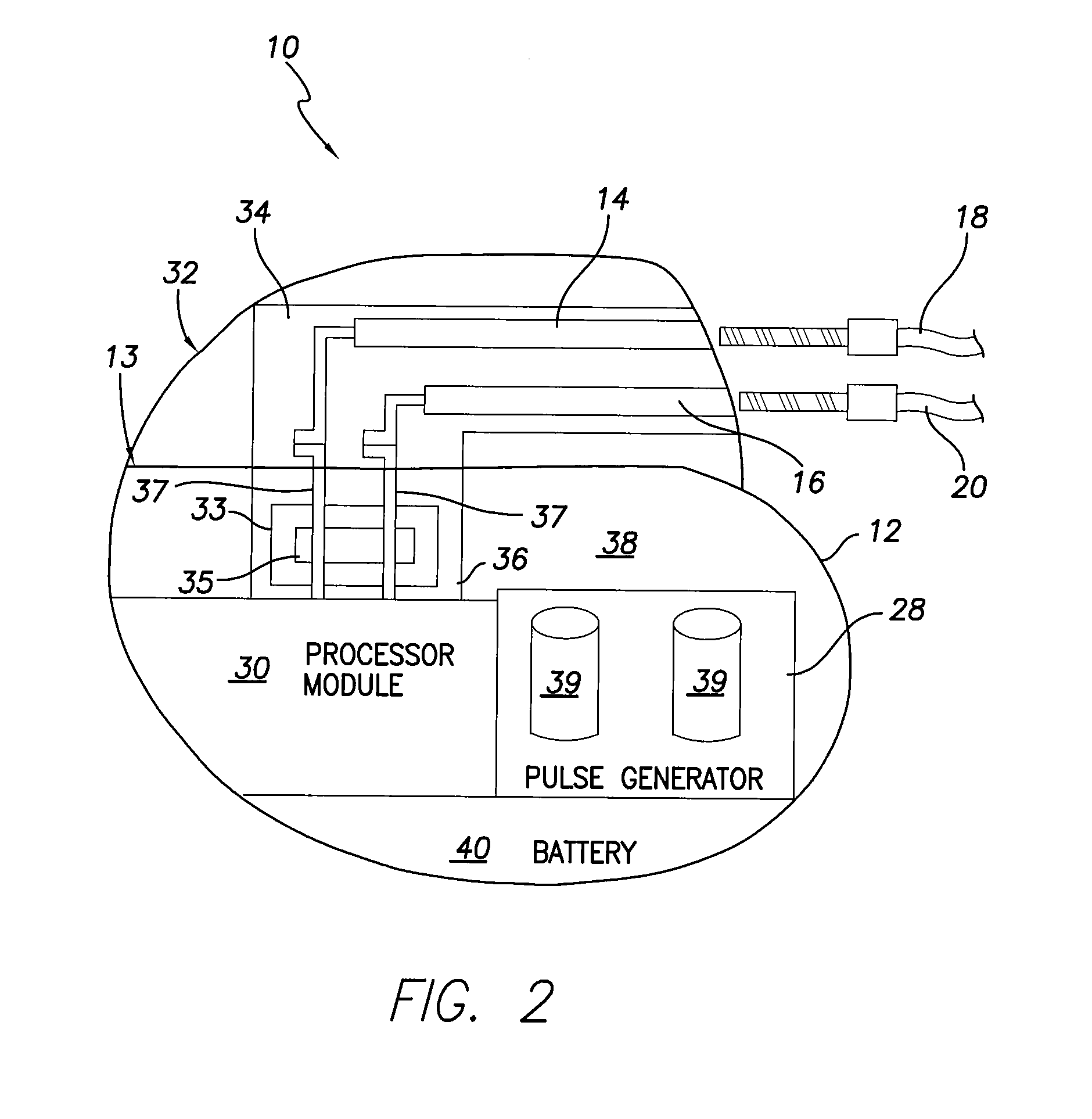
[0019]In the following detailed description, reference is made to the accompanying drawings which form a part hereof, and in which is shown by way of illustration specific embodiments in which the present invention may be practiced. These embodiments, which are also referred to herein as “examples,” are described in sufficient detail to enable those skilled in the art to practice the invention, and it is to be understood that the embodiments may be combined, or that other embodiments may be utilized and that structural, logical and electrical changes may be made without departing from the scope of the present invention. For example, embodiments may be used with a pacemaker, a cardioverter, a defibrillator, an appetite suppression device, a pain relief device, a muscle stimulation device, a nerve stimulation device and the like. The following detailed description is, therefore, not to be taken in a limiting sense, and the scope of the present invention is defined by the appended clai...


PUM


Abstract

An electromagnetic interference (EMI) filter is provided to attenuate potentially damaging high frequency electromagnetic interference from interfering with the operation of a hermetically sealed implantable medical device. In one embodiment, the EMI filter is joined to a bypass unit that is configured to provide an energy path for the delivery of an energy pulse. The bypass unit, in one embodiment, may include a non-linear device in parallel with an impedance component. The non-linear device can be a DIAC, a MOSFET, or any other non-linear semiconductor array. The EMI filter may be located within the header assembly, the feedthrough assembly, or located proximate to a pulse generator along the energy delivery path.

Description

FIELD OF THE INVENTION[0001]Embodiments of the present invention pertain generally to implantable medical devices, and more particularly pertain to implantable medical devices that utilize an electromagnetic interference filter to remove unwanted electrical noise.BACKGROUND OF THE INVENTION[0002]An implantable medical device is implanted in a patient to, among other things, monitor electrical activity of a heart and to deliver appropriate electrical and / or drug therapy, as required. Implantable medical devices (“IMDs”) include for example, pacemakers, cardioverters, defibrillators, implantable cardioverter defibrillators (“ICD”), and the like. The electrical therapy produced by an IMD may include, for example, pacing pulses, cardioverting pulses, and / or defibrillator pulses to reverse arrhythmias (e.g. tachycardias and bradycardias) or to stimulate the contraction of cardiac tissue (e.g. cardiac pacing) to return the heart to its normal sinus rhythm.[0003]In general, the IMD include...

Claims


Application Information

Patent Timeline
Patent Type & Authority Patents(United States)
IPC IPC(8): A61N1/16
CPCA61N1/37H03H1/0007A61N1/3718Y10S128/901
Inventor PROPATO, CLAUDIOMOUCHAWAR, GABRIEL A.SORENSEN, CHRIS
Owner PACESETTER INC
Why Eureka
Try Eureka