
Method for synthesis of carbon nanotubes

a carbon nanotube and carbon nanotube technology, applied in the direction of liquid gas reaction process, non-conductive material with dispersed conductive material, chemical/physical process, etc., can solve the problem of difficult to impregnate large quantities of iron, iron acetylacetonate is less effective than iron nitrate, and swnts are more difficult to manufacture than mwnts

Inactive Publication Date: 2009-11-24
ARKEMA FRANCE SA
View PDF20 Cites 41 Cited by
  • Summary
  • Abstract
  • Description
  • Claims
  • Application Information

AI Technical Summary

Benefits of technology

The present invention is about a process for synthesizing carbon nanotubes using a fluidized bed chemical vapor deposition method. This process involves injecting a carbon source onto a catalyst at a high temperature, resulting in the formation of nanotubes. The invention provides a method for increasing the productivity of carbon nanotube synthesis by controlling the state of aggregation of the catalyst and the carbon materials formed. The invention also provides a method for preparing a catalyst that can be supported on an inorganic substrate, which results in a multiplicity of catalytic sites varying in size between 3.5 and 70 nm. The invention also provides a method for synthesizing carbon nanotubes with a high degree of purity.

Problems solved by technology

In general, SWNTs are more difficult to manufacture than MWNTs.
It has also been found that iron acetylacetonate is less effective than iron nitrate.
Again in this document US 2001 / 0036549 A1, when a nonporous substrate, such as Degussa pyrolytic alumina, with a specific surface area of 100 m2 / g, is used, it is found to be difficult to impregnate large quantities of iron as only the external layer is accessible to the gas and the lower layers will exhibit insufficient catalytic activity.
Moreover, the technique using this kind of support is complicated since the particle size is 20 nm and the bulk density is 0.06, which increases the difficulty of industrial implementation.
Whatever the catalyst used, it has been found that synthesizing CNTs by CVD results in a limited productivity of the catalyst, which may be expressed by the ratio of the CNTs formed to the catalyst involved.
This limit is for example reached when all the available catalytic sites have reacted and / or when the entanglement of the CNTs around the support reduces the diffusion of the reactive gases (from the carbon source) to the catalytic sites, and reduces the catalyst area that can react.

Method used


Image

  • Method for synthesis of carbon nanotubes
  • Method for synthesis of carbon nanotubes
  • Method for synthesis of carbon nanotubes

Examples


example 1

Comparative Example—Preparation of CNTs by CVD According to the Prior Art: Step a) Only

[0058]A catalyst consisting of 35% iron was prepared by impregnating a Puralox SCCA 5-150 γ-alumina, having a median diameter of about 85 μm, with an iron nitrate solution. The impregnation was carried out in a fluidized bed with an air stream at 100° C. in order to keep the powder dry throughout the operation. 300 g of this catalyst were introduced as a layer in a 25 cm diameter reactor with an effective height of 1 m, the reactor being fitted with a disengagement device intended to prevent particle fines (fine catalyst particles) from being entrained downstream. The reactor was heated for 40 minutes at 300° C. under nitrogen, and then under hydrogen / nitrogen (20 vol % / 80 vol %), increasing the temperature up to 650° C. over 75 minutes. At this temperature, a 3000 Nl / h stream of ethylene and a 1000 Nl / h stream of hydrogen were introduced, this corresponding to an ethylene partial pressure of 0.75...

example 2

According to the Invention—Ex Situ Milling

[0063]The product obtained in Example 1 was subjected to tangential air jet milling in an apparatus sold by Alpine under the name Spiral jet mill 50 AS.

[0064]The gas flow rate and the injection time were set so as to reduce the agglomerates obtained according to Example 1 with a d50 of 40 μm.

[0065]A 5 g specimen of this milled product was introduced, under the CNT synthesis conditions according to Example 1, with an ethylene / hydrogen volume ratio of 3 / 1, into a 5 cm diameter reactor.

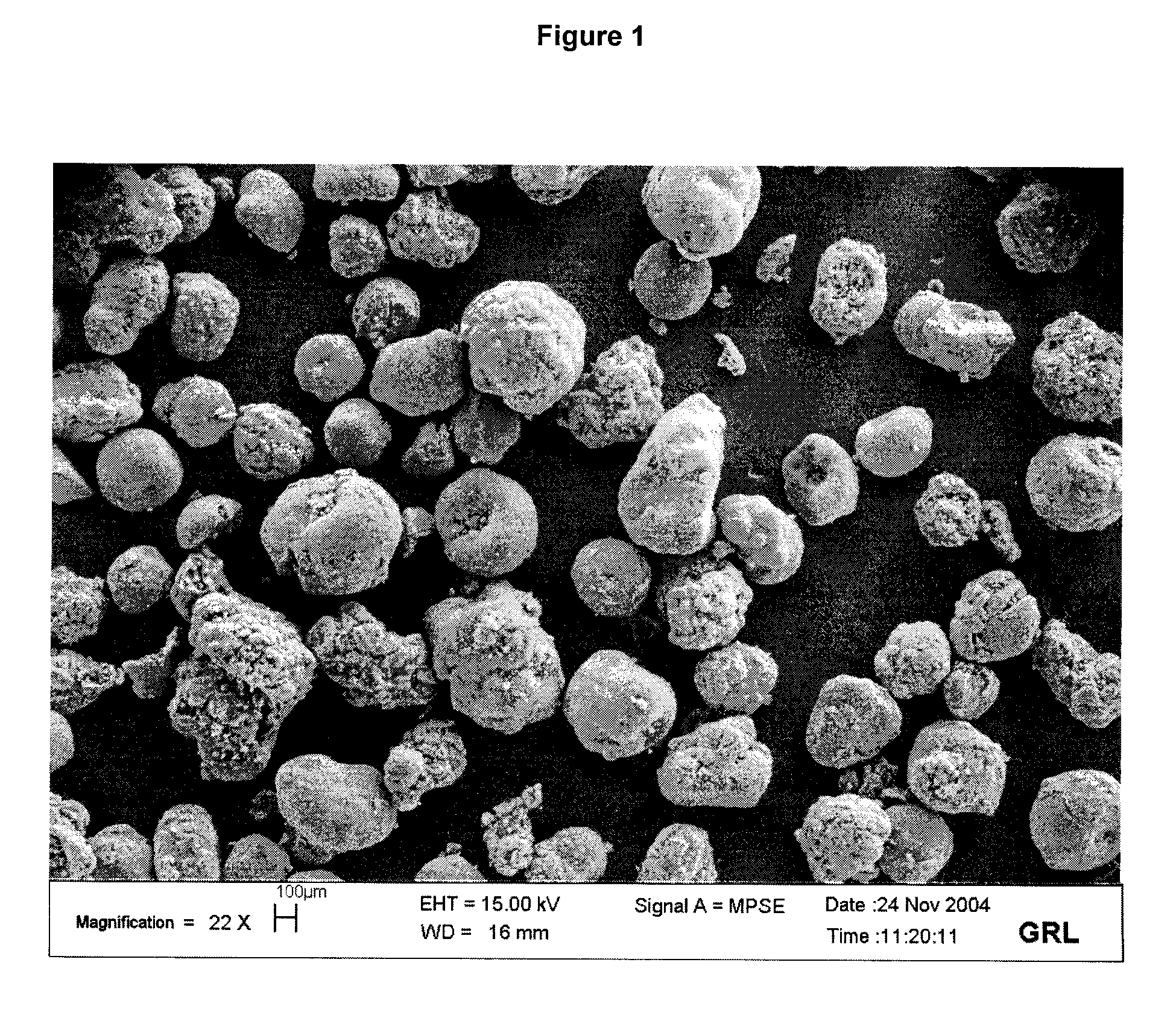
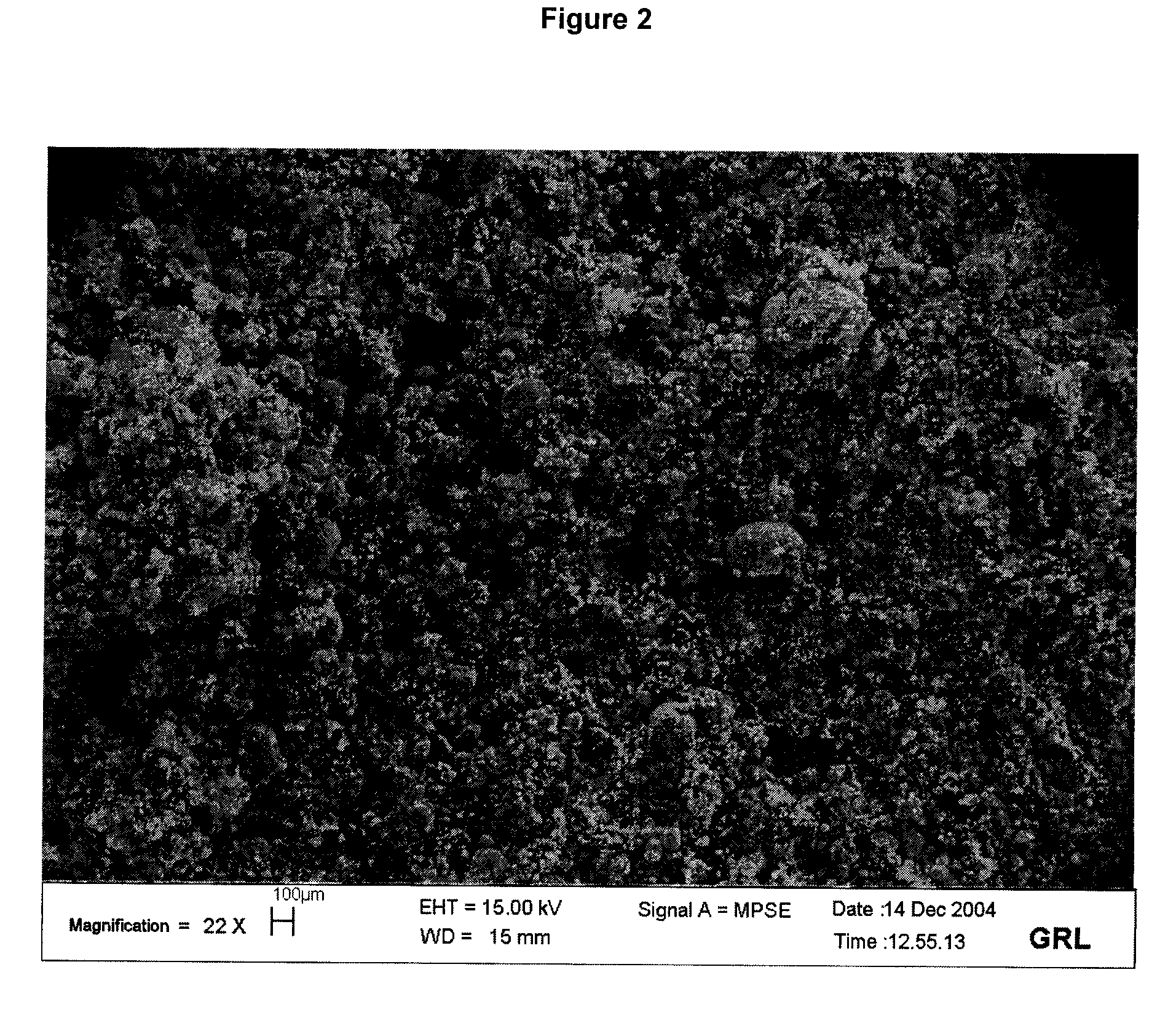
[0066]By comparing FIG. 2 with FIG. 1, it may be clearly seen that the process according to the invention results in a very small number of CNT agglomerates with a diameter greater than 200 μm. The final product thus formed is therefore more easily dispersed within a material, in particular a polymer.

[0067]At the end of synthesis, 6.4 g of final product were recovered, i.e. an increase of 28% (100×(6.4−5) / 5) with respect to the quantity of product introduced. The...

example 3

According to the Invention—In Situ Milling

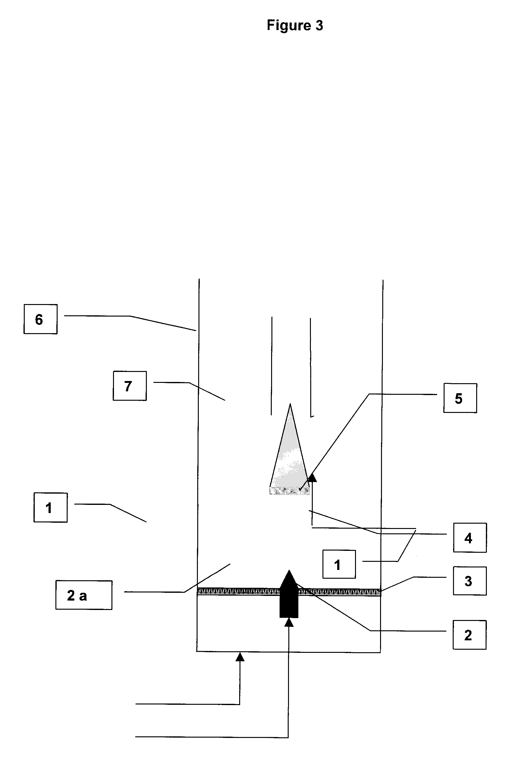
[0068]The product obtained in Example 1 was subjected to air jet milling directly in the synthesis reactor according to FIG. 3 appended hereto.

[0069]The milling was carried out at room temperature in the CNT synthesis reactor (6), which was a vertical tube 5 cm in diameter fitted with a porous distributor (3) equipped with a nozzle (2) for introducing high-velocity gas. The medium (7) was fluidized by a nitrogen stream (1) flowing through the distributor and a second stream (2a) passing through the nozzle (1).

[0070]The gas flow rate and the injection time were set to reduce the agglomerates obtained according to Example 1 with a d50 of 40 μm.

[0071]The final product thus obtained can be dispersed easily and homogeneously in a polymeric material, for the purpose of modifying its mechanical, electrical and / or thermal properties.


PUM

PropertyMeasurementUnit
temperatureaaaaaaaaaa
diameteraaaaaaaaaa

Abstract

The invention relates to a method for synthesis of carbon nanotubes of the highest carbon purity by the process of vapour phase chemical deposition. The nanotubes produced can be used to advantage in all know applications of carbon nanotubes.

Description

[0001]The subject of the present invention is a process for synthesizing carbon nanotubes (CNTs) by chemical vapor deposition, employing a fluidized catalyst bed.PRIOR ART[0002]Carbon nanotubes are recognized at the present time as being materials having great advantages because of their mechanical properties, their very high form factors (length / diameter ratios) and their electrical properties.[0003]They are made up from graphite sheets that are wound up and terminated by hemispheres consisting of pentagons and hexagons with a structure similar to fullerenes.[0004]Nanotubes are known to be composed of either a single sheet—referred to as single-walled nanotubes (SWNTs)—or of several concentric sheets—called multi-walled nanotubes (MWNTs). In general, SWNTs are more difficult to manufacture than MWNTs.[0005]Carbon nanotubes may be produced by various processes, such as electrical discharge, laser ablation or chemical vapor deposition (CVD).[0006]Among these techniques, the latter on...

Claims


Application Information

Patent Timeline
Patent Type & Authority Patents(United States)
IPC IPC(8): H01B1/04C01B31/02C09D7/61
CPCB82Y30/00C01B31/0233C09C1/56C09D5/24C09D7/1216C09D7/1283H01C17/0652H01G9/058H01G11/36C09C1/48B82Y40/00C01P2004/50C01B2202/30C01P2004/03C08K3/04Y02E60/13C01P2004/13C01B32/162C09D7/61C09D7/69H01G11/22C08K3/041
Inventor BORDERE, SERGEGAILLARD, PATRICEBADDOUR, CAROLE
Owner ARKEMA FRANCE SA
Learn More