Optical probe and optical tomography apparatus
a technology which is applied in the field of optical probes and optical tomography apparatuses, can solve the problems of preventing rapid measurement, requiring complicated manipulation, and obtaining high-quality tomography images only within narrow areas, and achieves large contact area, high-quality tomography images, and large contact area
- Summary
- Abstract
- Description
- Claims
- Application Information
AI Technical Summary
Benefits of technology
Problems solved by technology
Method used
Image

Examples
first embodiment
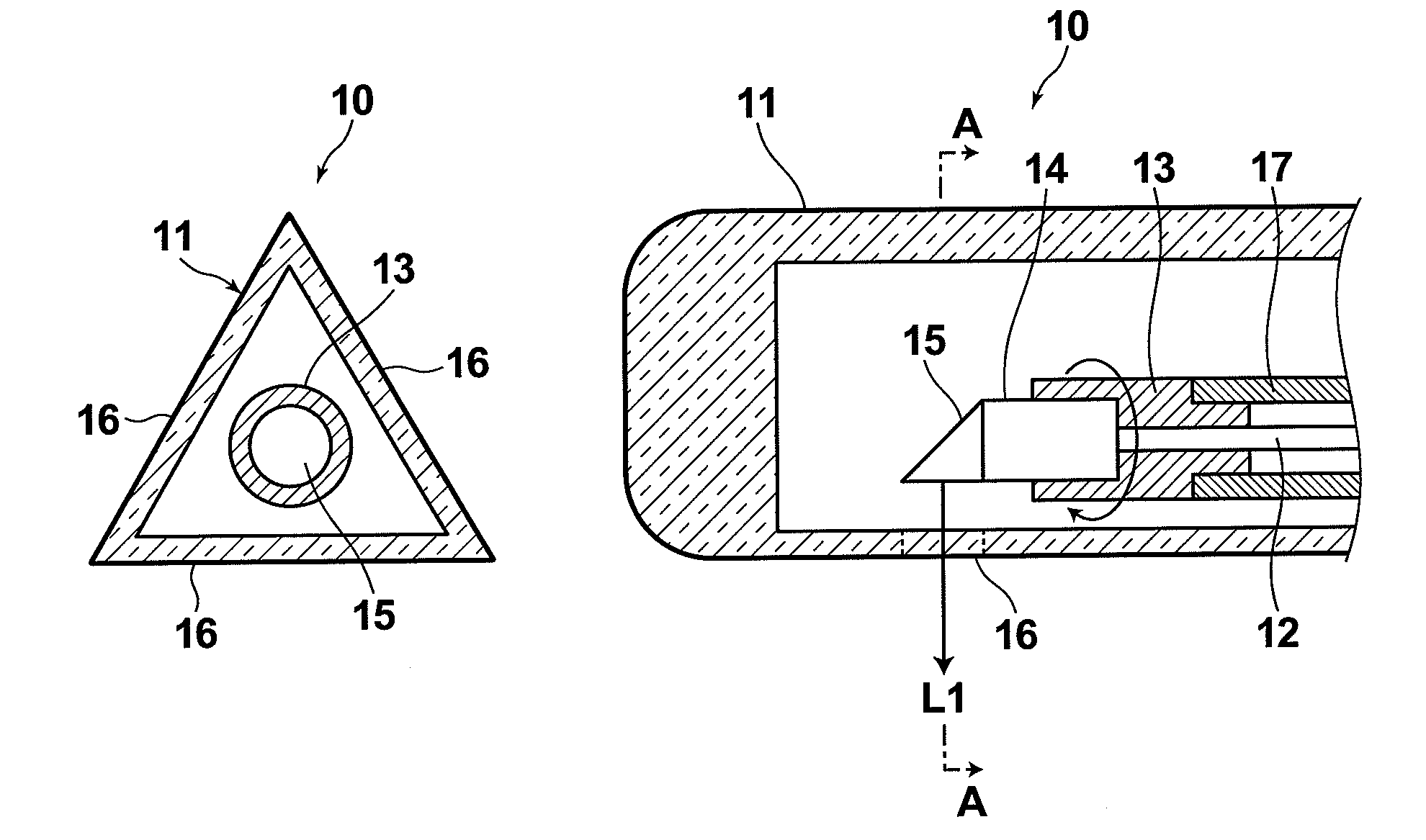
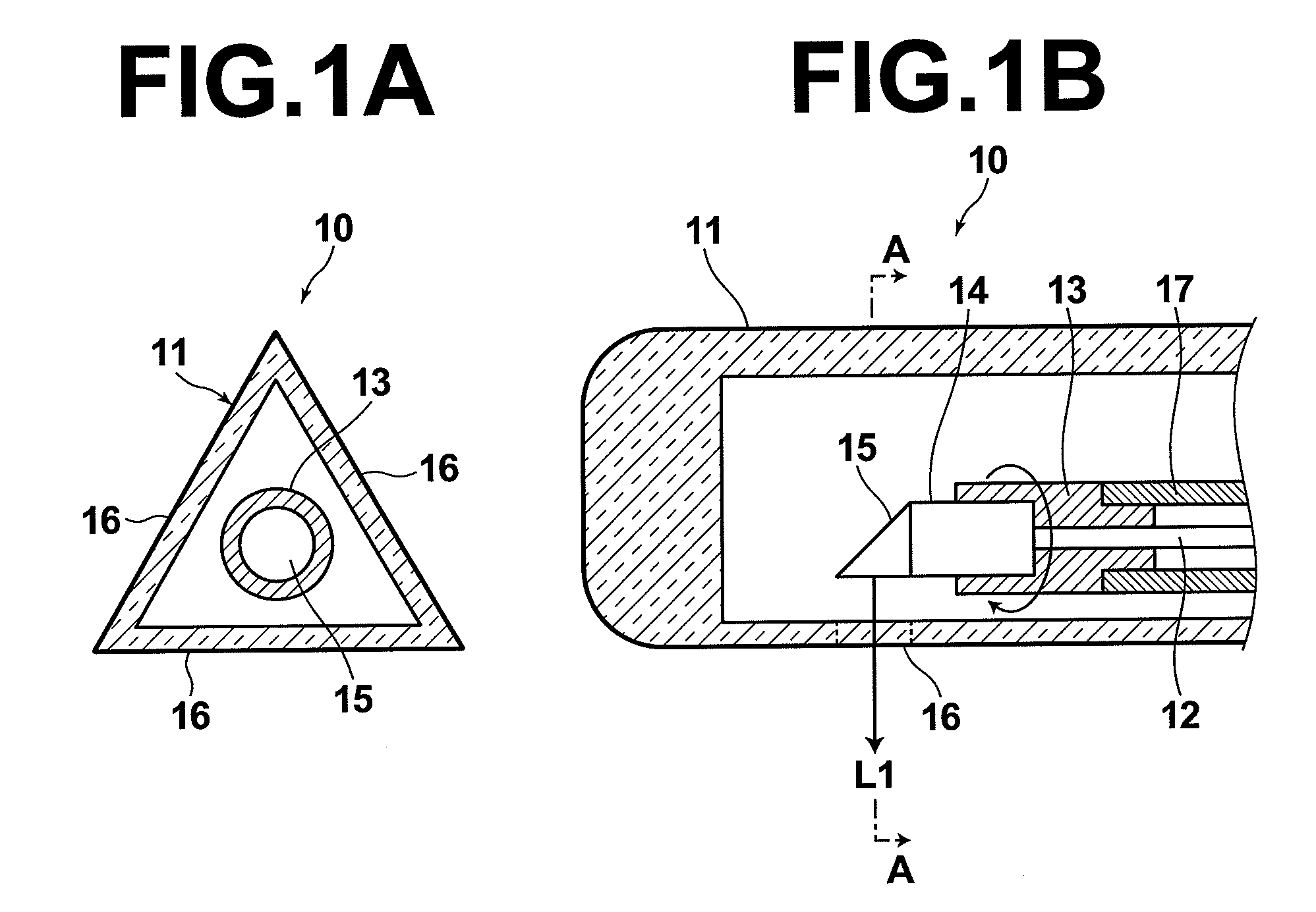
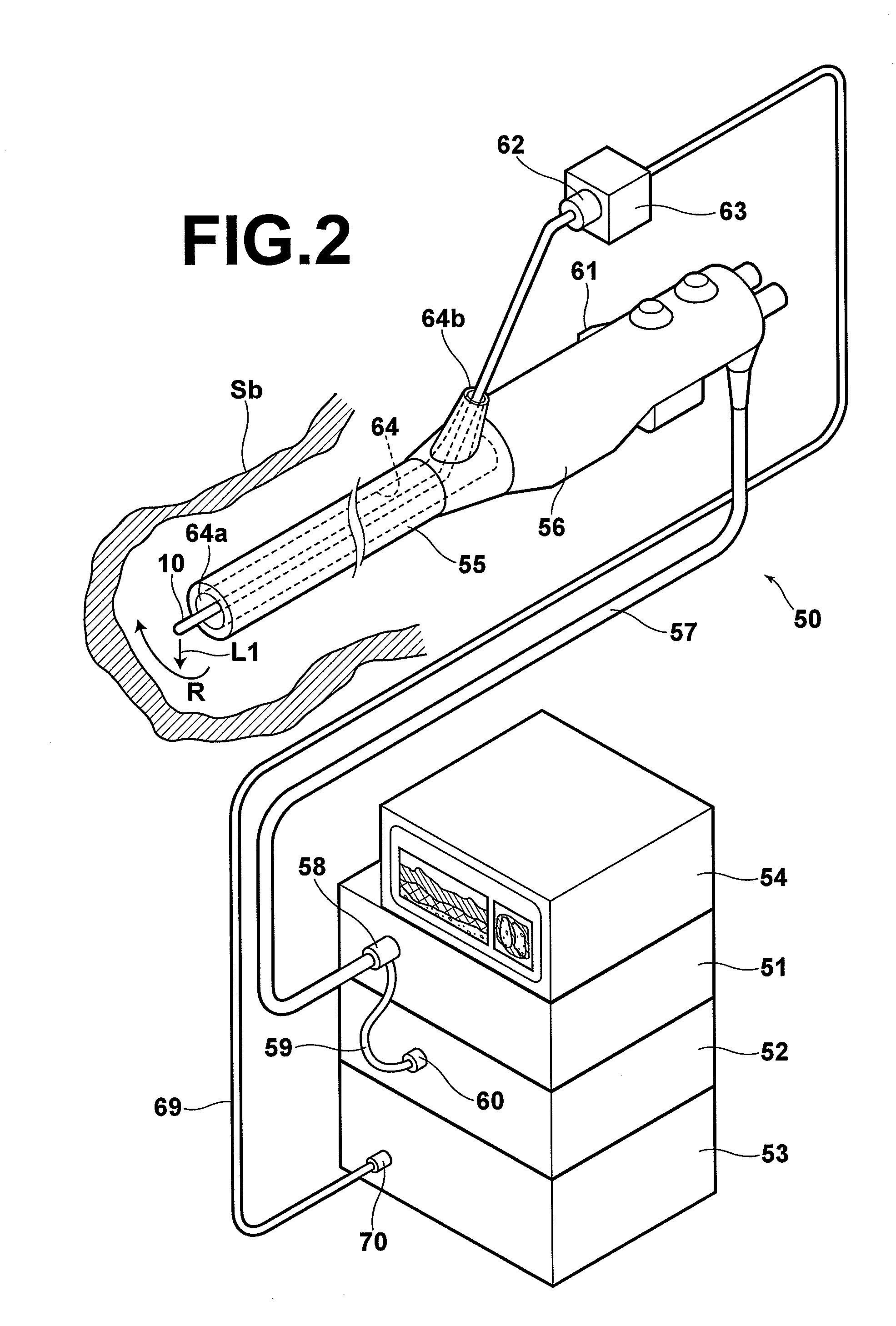
[0067]Hereinafter, exemplary embodiments of the present invention will be described with reference to the accompanying drawings. FIGS. 1A and 1B are schematic cross-sectional view and schematic side cross-sectional view of an optical probe 10 according to the present invention respectively. The optical probe 10 is to be inserted into a forceps channel 64 of an endoscope constituting an optical tomography apparatus, the overall configuration of which is illustrated in FIG. 2.
[0068]First, the outline of the optical tomography apparatus will be described with reference to FIG. 2. The apparatus includes: an endoscope 50 having an optical probe 10; a light source unit 51 to which the endoscope 50 is connected; a video processor 52; optical tomography processing unit 53; and a monitor 54 connected to the video processor 52. The endoscope 50 includes a flexible elongated insertion section 55, an operation section 56 connected to the proximal end of the insertion section 55, and a universal...
second embodiment
[0129]Hereinafter, example optical probes formed of a plurality of members will be described. First, the optical probed will be described with reference to FIGS. 10A and 10B. FIG. 10B is a side cross-sectional view of an optical probe 80 having a sheath 83 which includes a cylindrical sheath body 81, and a cap member 82 which is a cap-like member for covering the distal end section of the sheath body 81. FIG. 10A is a cross-sectional view taken along the line B-B in FIG. 10B.
[0130]The optical fiber 12, fixing member 13, GRIN lens 14, and prism mirror 15 are disposed in the internal space of the sheath body 81, as in the first embodiment.
[0131]The cap member 82 is removably attached to the sheath body 81 by a thread section 84 formed on the circumferential surface thereof. The cap member 82 may be formed, for example, in an angular tube such that the outer shape in cross-section which is perpendicular to the longitudinal direction of the optical probe 80 becomes an equilateral trian...
third embodiment
[0135]Next, the optical probe will be described with reference to FIGS. 12A and 12B. FIG. 12B is a side cross-sectional view of an optical probe 90 having a sheath 93 which includes a cylindrical sheath body 91, and a strip-like member 92. FIG. 12A is a cross-sectional view taken along the line C-C in FIG. 12B.
[0136]The optical fiber 12, fixing member 13, GRIN lens 14, and prism mirror 15 are disposed in the internal space of the sheath body 81, as in the first embodiment.
[0137]The strip-like member 92 is removably attached to the sheath body 91 by a click section 94. The click section 94 shown in FIG. 12B includes a protrusion provided on the sheath body 91 and a groove provided on the strip-like member 92 such that it engages with the protrusion.
[0138]The strip-like member 92 may be formed, for example, in an angular tube such that the outer shape in cross-section which is perpendicular to the longitudinal direction of the optical probe 90 becomes an equilateral triangle shown in...
PUM
 Abstract
Description
Claims
Application Information
 - R&D
- Intellectual Property
- Life Sciences
- Materials
- Tech Scout
- Unparalleled Data Quality
- Higher Quality Content
- 60% Fewer Hallucinations
Browse by: Latest US Patents, China's latest patents, Technical Efficacy Thesaurus, Application Domain, Technology Topic, Popular Technical Reports.
© 2025 PatSnap. All rights reserved.Legal|Privacy policy|Modern Slavery Act Transparency Statement|Sitemap|About US| Contact US: help@patsnap.com