Ignition spark plug

a spark plug and ignition technology, applied in the direction of spark plugs, machines/engines, mechanical equipment, etc., can solve the problems of increasing the damage caused by nitrogen oxides (nox), the output power of the engine cannot reduce the harmful effects of nitrogen oxides (nox) on the human body, and the accumulation of unburned hydrocarbons due to the three-way catalytic converter. , to achieve the effect of increasing the life of the ignition plug, preventing abnormal ignition, and easy transfer

Inactive Publication Date: 2009-12-08
JOHNG IN TAE
View PDF9 Cites 25 Cited by
  • Summary
  • Abstract
  • Description
  • Claims
  • Application Information

AI Technical Summary

Benefits of technology

[0028]The above-described ignition plug according to the present invention has the following effects.
[0029]First, the cross flame ignition valve is not deformed even under high-temperature and high-pressure conditions because it is manufactured using a zirconium-based alloy. Accordingly, there are advantages in that it is possible to increase the life span of the ignition plug and to prevent abnormal ignition caused by high-temperature heat.
[0030]Second, there is an advantage in that it is possible to easily transfer high-temperature heat generated in the primary combustion chamber to the external of the ignition plug by virtue of the heat transfer member interposed between the inner wall surface of the main cell and the insulator. It is also possible to prevent flames from being leaked through a gap defined between the main cell and the insulator.
[0031]Third, there is an advantage of easy assembly of the ignition plug because the cross flame ignition valve is coupled to the lower end of the main cell by simply bending the extension part.
[0032]Fourth, it is possible to increase the combustion rate of the gas mixture because the cross flame ignition valve has high resistance to high temperature. In accordance with the increased gas mixture combustion rate, it is possible to obtain high engine output power. There is also an advantage in that it is possible to enable delayed ignition in the overall stroke of the engine. In addition, there are advantages of an extended life span of engine oil, a reduction in the noise and vibration generated in the engine, and a reduction in the emission of exhaust gas, in particular, nitrogen oxides.

Problems solved by technology

However, the mechanism for obtaining the maximum output power of the engine cannot reduce nitrogen oxides (NOx) harmful to the human body.
In particular, the problem caused by nitrogen oxides (NOx) becomes more severe in vehicles using LPG (a gas mixture of propane and butane).
In this case, however, unburned hydrocarbon is accumulated due to the three-way catalytic converter.
As a result, the system may be blocked or damaged.
However, the proposed structures incur a reduction in fuel efficiency, misfire caused by overheat at the TDP, and abnormal ignition.
As a result, there is another problem such as a reduction in output power or a degradation in operation performance in the case of a high-performance engine.
Furthermore, the lower end of the pre-combustion chamber in such an ignition plug for example, an encapsulated cover, may be overheated beyond the heat exchange capability of the ignition plug namely, the heat range of the ignition plug due to high-temperature heat and vortex heat source gas present in the cylinder.
Due to such overheat, detonation such as earlier ignition in a compression stroke may occur.
As a result, a phenomenon that the engine is abruptly stopped may occur.

Method used


Image

  • Ignition spark plug
  • Ignition spark plug
  • Ignition spark plug

Examples


Embodiment Construction

[0033]The accompanying drawings, which are included to provide a further understanding of the invention, illustrate embodiments of the invention and together with the description serve to explain the principle of the invention.

[0034]In the drawings:

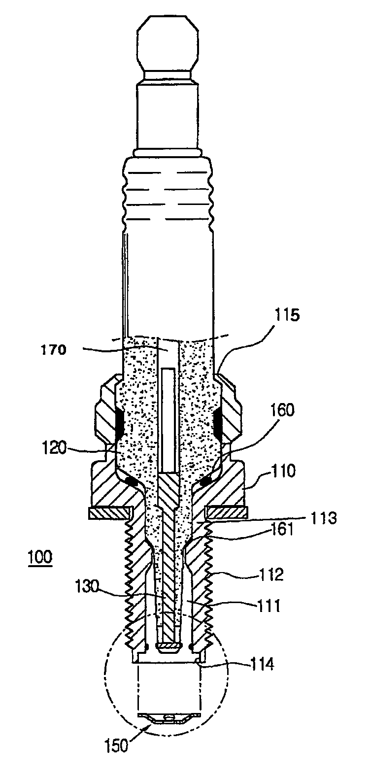
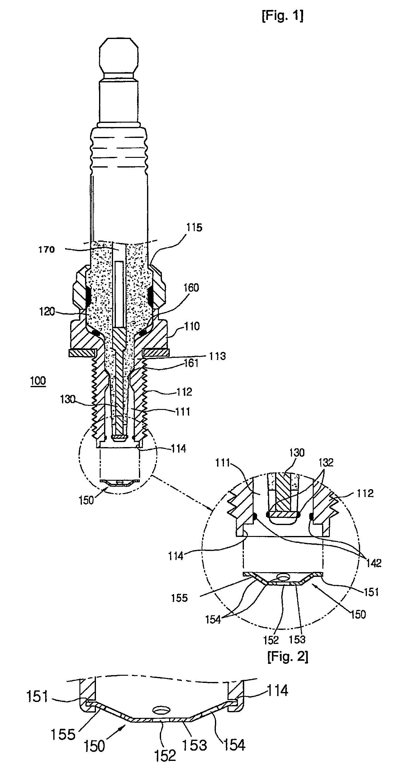
[0035]FIG. 1 is a sectional view illustrating the ignition plug according to the present invention;

[0036]FIG. 2 is an enlarged sectional view illustrating a coupled state of a cross flame ignition valve included in the ignition plug of FIG. 1 in accordance with an embodiment of the present invention; and

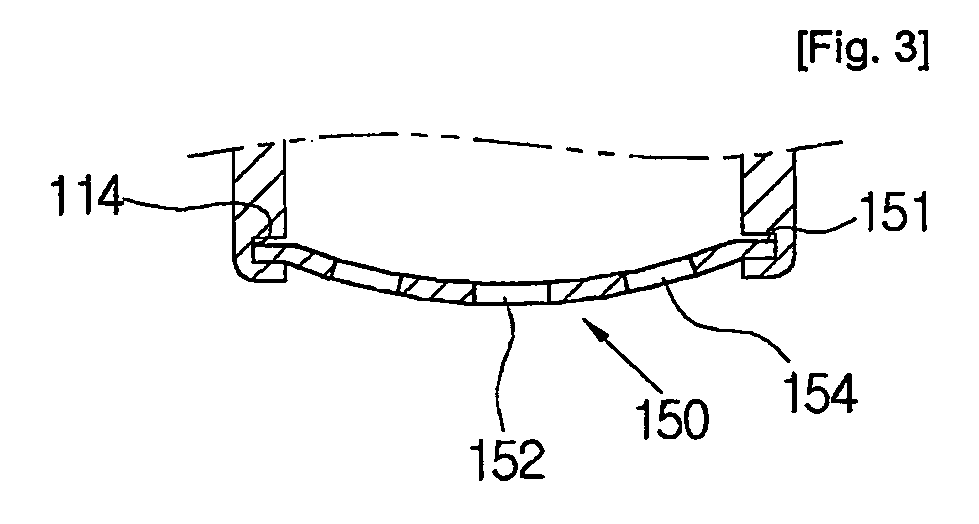
[0037]FIG. 3 is an enlarged sectional view illustrating a coupled state of a cross flame ignition valve included in the ignition plug in accordance with another embodiment of the present invention.

[0038]Reference will now be made in detail to preferred embodiments of an ignition plug according to the present invention, examples of which are illustrated in the accompanying drawings. FIG. 1 is a sectional view illustrating the ignition plug ...


PUM


Abstract

An ignition plug is disclosed which includes a hollow main cell having a bendable extension part and a primary combustion chamber, an insulator mounted in the main cell, to insulate a terminal rod centrally embedded in the main cell, a central electrode having a first electrical contact arranged in the primary combustion chamber, the central electrode extending downwardly from the terminal rod while being surrounded by the insulator, a second electrical contact provided at a lower inner surface of the main cell while being arranged in the primary combustion chamber, the second electrical contact corresponding to the first electrical contact, and a cross flame ignition valve coupled to the main cell by the extension part in a bent state of the extension part, the cross flame ignition valve having a main ignition hole and auxiliary ignition holes for guiding flames from the primary combustion chamber to an interior of a cylinder.

Description

TECHNICAL FIELD[0001]The present invention relates to an ignition device, and more particularly, to an ignition plug for an internal combustion engine which is capable of enhancing the combustion performance of the combustion engine and reducing a generation of nitrogen oxides (NOx), while being used for a prolonged period of time.BACKGROUND ART[0002]Internal combustion engines, which are mainly used as vehicle engines, may be classified into a 4-cycle engine and a 2-cycle engine. The 4-cycle engine has a compression stroke, a suction stroke, a combustion stroke, and an exhaust stroke.[0003]Such an internal engine uses an ignition plug in order to burn a gas mixture in a combustion stroke. That is, the ignition plug means a spark discharge device for igniting a gas mixture compressed in an internal engine.[0004]Generally, where such an ignition plug is used in spark ignition type internal combustion engine using high-octane gasoline, the ignition timing point of the ignition plug sh...

Claims


Application Information

Patent Timeline
Patent Type & Authority Patents(United States)
IPC IPC(8): H01T13/20H01T13/46H01T13/54
CPCH01T13/20H01T13/54H01T13/467H01T13/39F02P13/00
Inventor JOHNG, IN TAE
Owner JOHNG IN TAE
Why Eureka
Try Eureka