On-chip temperature sensor

a temperature sensor and chip technology, applied in the field of temperature sensing in an integrated circuit, can solve the problems of power waste, cell loss of charge ability,

Active Publication Date: 2009-12-08
MICRON TECH INC
View PDF5 Cites 16 Cited by
  • Summary
  • Abstract
  • Description
  • Claims
  • Application Information

AI Technical Summary

Problems solved by technology

As the device heats up, the cells lose their ability to hold a charge due to current leakage.
However, the faster refresh rate is not required when the device is operating at a cooler temperature, thus wasting power.

Method used


Image

  • On-chip temperature sensor
  • On-chip temperature sensor
  • On-chip temperature sensor

Examples


Embodiment Construction

[0019]In the following detailed description, reference is made to the accompanying drawings that form a part hereof, and in which is shown, by way of illustration, specific embodiments. In the drawings, like numerals describe substantially similar components throughout the several views. These embodiments are described in sufficient detail to enable those skilled in the art to practice the invention. Other embodiments may be utilized and structural, logical, and electrical changes may be made without departing from the scope of the present invention. The following detailed description is, therefore, not to be taken in a limiting sense, and the scope of the embodiments is defined only by the appended claims and equivalents thereof.

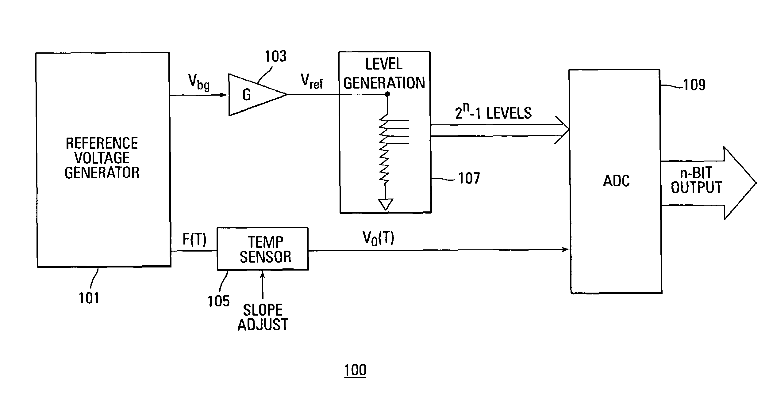
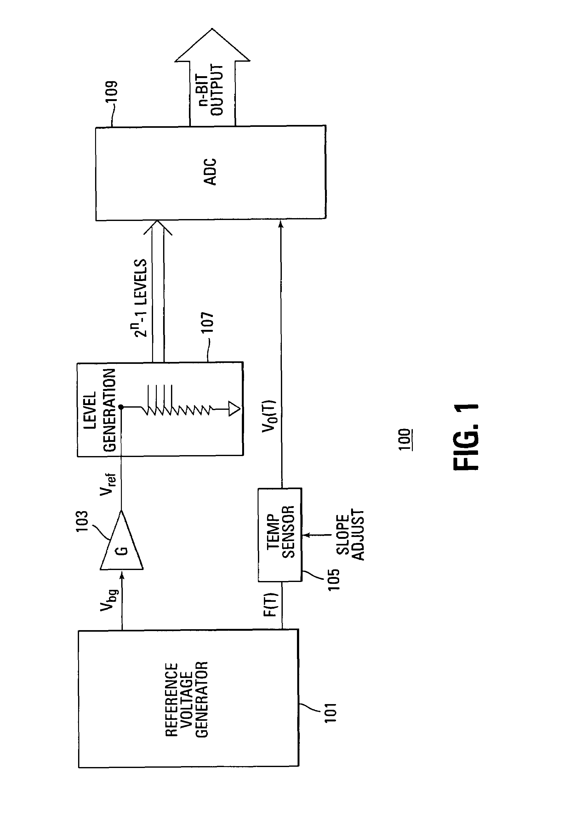
[0020]FIG. 1 illustrates a block diagram of one embodiment of a temperature sensing circuit 100. The circuit is comprised of a reference voltage generator circuit 101 that outputs a temperature invariant voltage Vbg and a temperature variant value F(T). The...


PUM


Abstract

A temperature invariant reference voltage and a temperature variant physical quantity, such as a voltage or current, are generated. The temperature variant physical quantity changes in response to a temperature of the integrated circuit. A temperature sensor circuit generates a voltage that is linearly dependent on the temperature. A level generator circuit generates 2n−1 voltage levels from the reference voltage. A comparator circuit, such as an analog-to-digital circuit, compares the voltage from the temperature sensor to the 2n−1 voltage levels to determine which level is closest. An n-bit digital output of the resulting level is proportional to the temperature of the integrated circuit.

Description

RELATED APPLICATION[0001]This application claims priority to Italian Patent Application Serial No. RM2006A000675, filed Dec. 14, 2006, entitled “ON-CHIP TEMPERATURE SENSOR,” which is commonly assigned.TECHNICAL FIELD OF THE INVENTION[0002]Embodiments of the present invention relate generally to temperature sensing and more particularly to temperature sensing in an integrated circuit.BACKGROUND OF THE INVENTION[0003]It is sometimes desirable to know the internal temperature of integrated circuits. The integrated circuit temperature can be used to improve circuit operation by compensating signals that change from nominal operation when the chip temperature changes.[0004]For example, in a non-volatile memory device such as a NAND flash memory, programming and reading memory cell data requires various voltages for programming the cell to a desired threshold voltage and then applying that threshold voltage to the cell to determine if the cell turns on and conducts. If the cell does not t...

Claims


Application Information

Patent Timeline
Patent Type & Authority Patents(United States)
IPC IPC(8): G11C7/04
CPCG01K7/01G11C11/40626G11C7/04G01K2219/00G11C11/406
Inventor MACEROLA, AGOSTINOMAROTTA, GIULIO-GIUSEPPETIBURZI, MARCO-DOMENICO
Owner MICRON TECH INC
Why Eureka
Try Eureka