Film forming method employing reactive and reducing gases and substrate formed by the method

a film forming and reactive technology, applied in the field of film forming, can solve the problems of high cost, troublesome wastewater treatment with plating operation, limited metals which are capable of being plated, etc., and achieve the effects of low cost, large film forming rate, and simple facilities or operation process

Inactive Publication Date: 2009-12-15
KONICA CORP
View PDF34 Cites 32 Cited by
  • Summary
  • Abstract
  • Description
  • Claims
  • Application Information

AI Technical Summary

Benefits of technology

[0007]The present invention was made in view of the above-described problem. An object of the present invention is to provide a film forming method capable of obtaining good films of various kinds of metals that requires only s

Problems solved by technology

However, with respect to the wet plating methods, the kinds of metals which are capable of being plated are limited.
Further, troublesome wastewater treatment is required with plating operation.
Further, with respect to the dry plating methods, since huge facilities to make a vacuum state are generally required, cost is high, and moreover, there is a problem that the film forming rate is slow.
With resp

Method used


Image

  • Film forming method employing reactive and reducing gases and substrate formed by the method
  • Film forming method employing reactive and reducing gases and substrate formed by the method
  • Film forming method employing reactive and reducing gases and substrate formed by the method

Examples


example 1

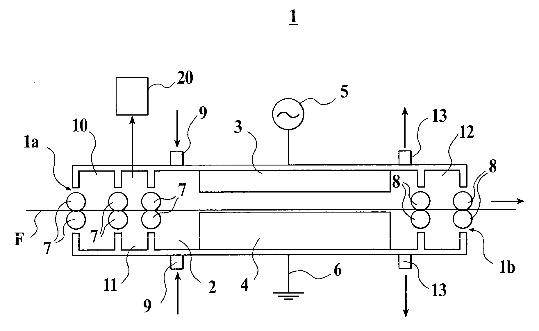
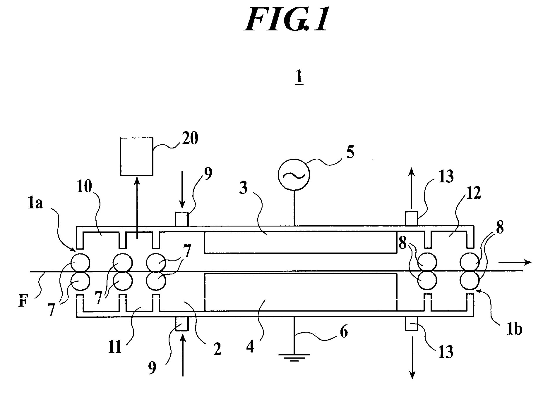
[0073]A metal film was formed as follows by using the plasma treatment device 1 shown in FIG. 1. Here, the electrodes 3 and 4 have stainless steel SUS 316 as their base material, respectively. This base material is constructed so as to be capable of circulating heat-insulating water.

[0074]An alumina ceramic was sprayed over the whole surface of the base material of stainless steel in a thickness of 1 mm to cover around the base material except both side surfaces of the base material in a longitudinal direction. Thereafter, embrocation in which alkoxysilane monomer was dissolved in an organic solvent was applied to the above-described ceramic film and dried. Then, it was heat-treated at 150° C. to provide a dielectric. A high-frequency voltage was applied to the electrode 3 by the surface without the film, and the electrode 4 was connected to an earth. The distance between the electrodes 3 and 4 is 1 mm.

[0075]A film F as a substrate was passed between the electrodes 3 and 4 as shown ...

example 2

[0084]A copper film was formed just as the same way as the Example 1 except further superimposing pulse voltage (10 kHz, on time / off time=0.5) to the high-frequency power source 5.

example 3

[0092]A copper film was formed just the same way as in the Example 1 including the composition of the reactive gas, reducing gas and the like except the following electric conditions. A voltage having frequency of 200 kHz, and power of 1.2 W / cm2 was applied between the electrodes 3 and 4 in FIG. 1.


PUM

PropertyMeasurementUnit
Percent by volumeaaaaaaaaaa
Pressureaaaaaaaaaa

Abstract

A film forming method comprising: supplying a reactive gas comprising a compound including a metal atom between facing electrodes; arranging a substrate between the electrodes; making the reactive gas in a plasma state by applying a voltage between the electrodes under atmospheric pressure or under a pressure in a vicinity of the atmospheric pressure and discharging; and forming a metal film on a surface of the substrate by supplying a reducing gas having a reducing property into a plasma atmosphere in which the reactive gas in the plasma state exists.

Description

BACKGROUND OF THE INVENTION[0001]1. Field of the Invention[0002]The present invention relates to a film forming method for forming a metal film on a surface of a substrate by making a reactive gas into plasma under atmospheric pressure or under a pressure in the vicinity of atmospheric pressure, and to a substrate having a metal film formed by the above-described film forming method.[0003]2. Description of Related Art[0004]In earlier technology, as methods for forming a metal film, which is used as an electrode or the like, on a substrate, there are wet plating methods, such as electroplating, nonelectrolytic plating and the like, dry (vapor) plating methods, such as vacuum deposition, sputtering, ion plating, MOCVD (Metal organic chemical vapor deposition) and the like, plasma spraying, and the like.[0005]However, with respect to the wet plating methods, the kinds of metals which are capable of being plated are limited. Further, troublesome wastewater treatment is required with pla...

Claims


Application Information

Patent Timeline
IPC IPC(8): C23C16/06H05H1/24H05H1/46C23C16/18C23C16/509C23C16/54
CPCC23C16/18C23C16/545C23C16/5096
Inventor MIZUNO, WATARUFUKUDA, KAZUHIROKONDO, YOSHIKAZUTODA, YOSHIROOISHI, KIYOSHINISHIWAKI, AKIRA
Owner KONICA CORP
Why Eureka
Try Eureka