Pumping system

a pumping system and pumping technology, applied in the direction of piston pumps, positive displacement liquid engines, borehole/well accessories, etc., can solve the problems of low effective load factor level, high power consumption, and inferior movement performance, so as to reduce the weight of the pumping system, improve the pump movement performance, and reduce power consumption

Active Publication Date: 2009-12-22
PETROCHINA CO LTD +1
View PDF11 Cites 9 Cited by
  • Summary
  • Abstract
  • Description
  • Claims
  • Application Information

AI Technical Summary

Benefits of technology

[0004]In order to overcome such disadvantages of conventional pumping units as inferior movement performance, low level of effective load factors, high power consumption, large dimensions, high weights, high capital investments, high operating costs, and high labor intensity in parameter adjustments and testing, the present invention provides a pumping system that not only operates with good movement performance, high level of effective load factor, and low power consumption, but also features relatively small dimensions and low weight of the unit, less capital investment, relative ease of parameter adjustments and testing operations, and the elimination of rigid rods. Further, the pumping unit of the present invention is a multifunctional pumping system that has multiple pumping, operating and testing capabilities, and does not need special operational derricks and rigs during operations to replace the plunger, but rather can execute tripping operations by using its own driving power.
[0007]The beneficial effects of this invention include the following: because the pumping system of this invention employs the abovementioned configuration and component elements, by utilizing the characteristics of up and down reciprocal movement of dual pumps on the flexible cable driven by the movable pulley(s) on the crank, the circular motion of the crank can be directly converted into up and down reciprocal motion of the flexible driving body, thereby making it possible for the rigid sucker rod and walking beam of conventional oil field pumping units to be eliminated. This modification reduces the weight of the pumping system and doubles the maximum stroke, hence, during operations, improving pump movement performance, reducing power consumption, increasing the effective load factor, and allowing the oil well pump to realize the desired purpose of lifting. Furthermore, because the structure of the pumping system of the present invention is simple and compact and eliminates the rigid rod, it is possible to reduce the dimensions of the unit, the self weight, and the one-off investment, at the same time. Because the other end of the cable may be connected to the tester, it can carry out an equipment test through the tester without the need to shut down the machine, thereby simplifying the test process. Secondly, by changing the position of the fixed end of the cable and the transmission ratio of the speed reducer, it is possible to perform the operations of adjusting the stroke of the pumping system without shutdown and with a minimal number of stroke adjustments.
[0008]It can thus be seen that this invention provides an improved pumping system, in particular, a single-crank, double-stroke, flexible-cable pumping apparatus, which does not need special operational derricks and rigs during operations for replacing the plunger, but rather can execute tripping operations by using its own driving power. During regular operations, the pumping system of this invention not only offers good movement performance, high level of effective load factor, and low power consumption, but also features relatively small unit dimensions and self weight, less one-off investment, ease of parameter adjustments and test operations, and elimination of the rigid sucker rod.

Problems solved by technology

Such conventional pumping units of the abovementioned structures and models are typically characterized by inferior movement performance, low level of effective load factors, and high power consumption.
Also, because these conventional pumping units generally have large dimensions and relatively high weights, they need robust foundations and therefore relatively high capital investments.
Furthermore, the labor intensity involved in carrying out periodic parameter adjustments and balance adjustments is relatively high.

Method used


Image

  • Pumping system
  • Pumping system
  • Pumping system

Examples


Embodiment Construction

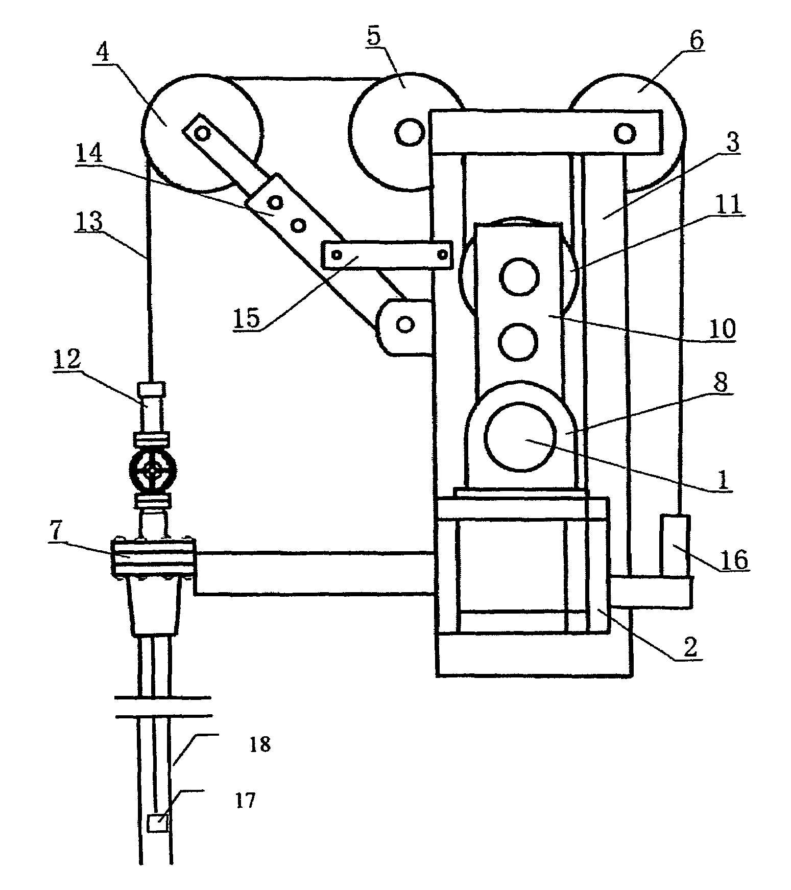
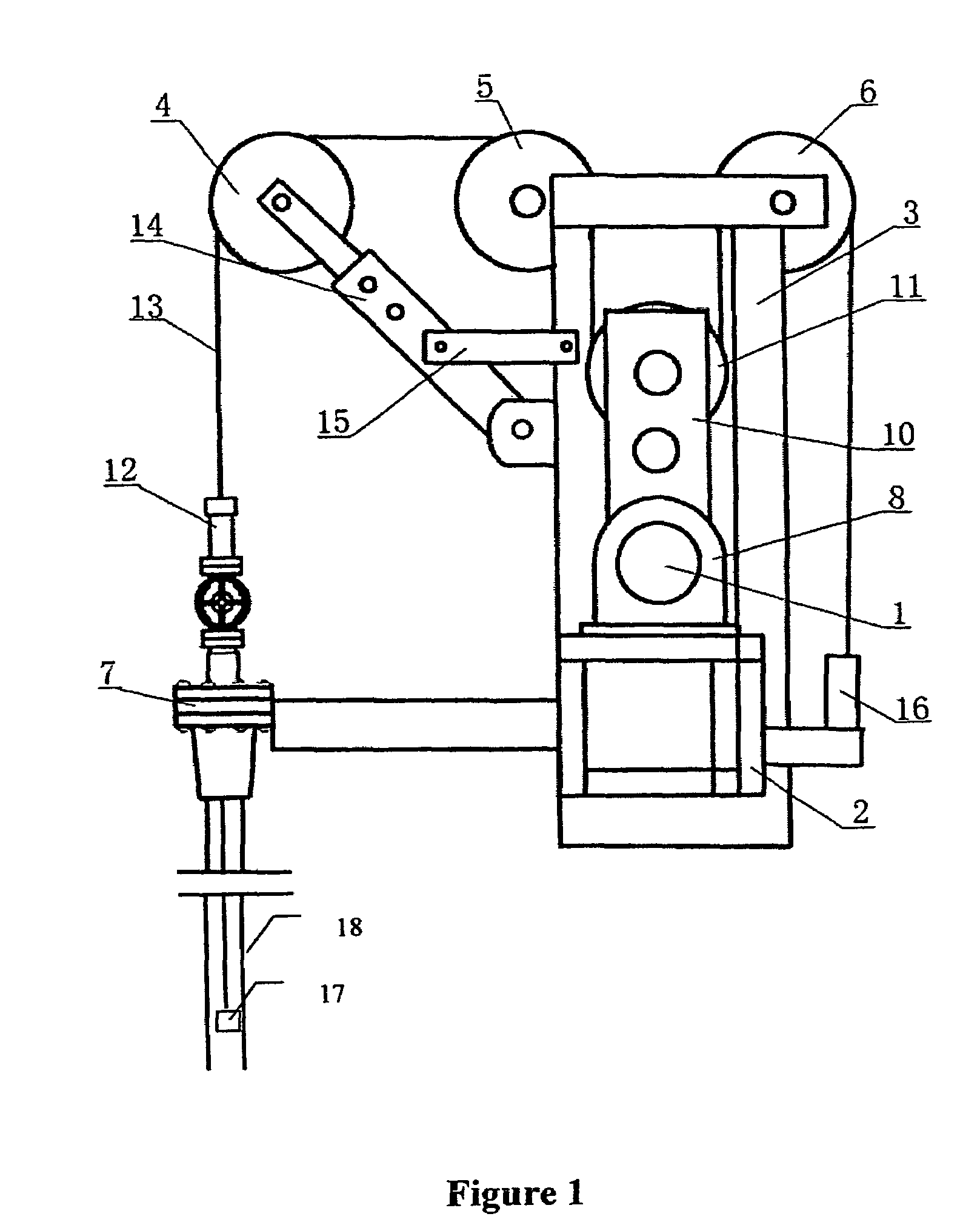
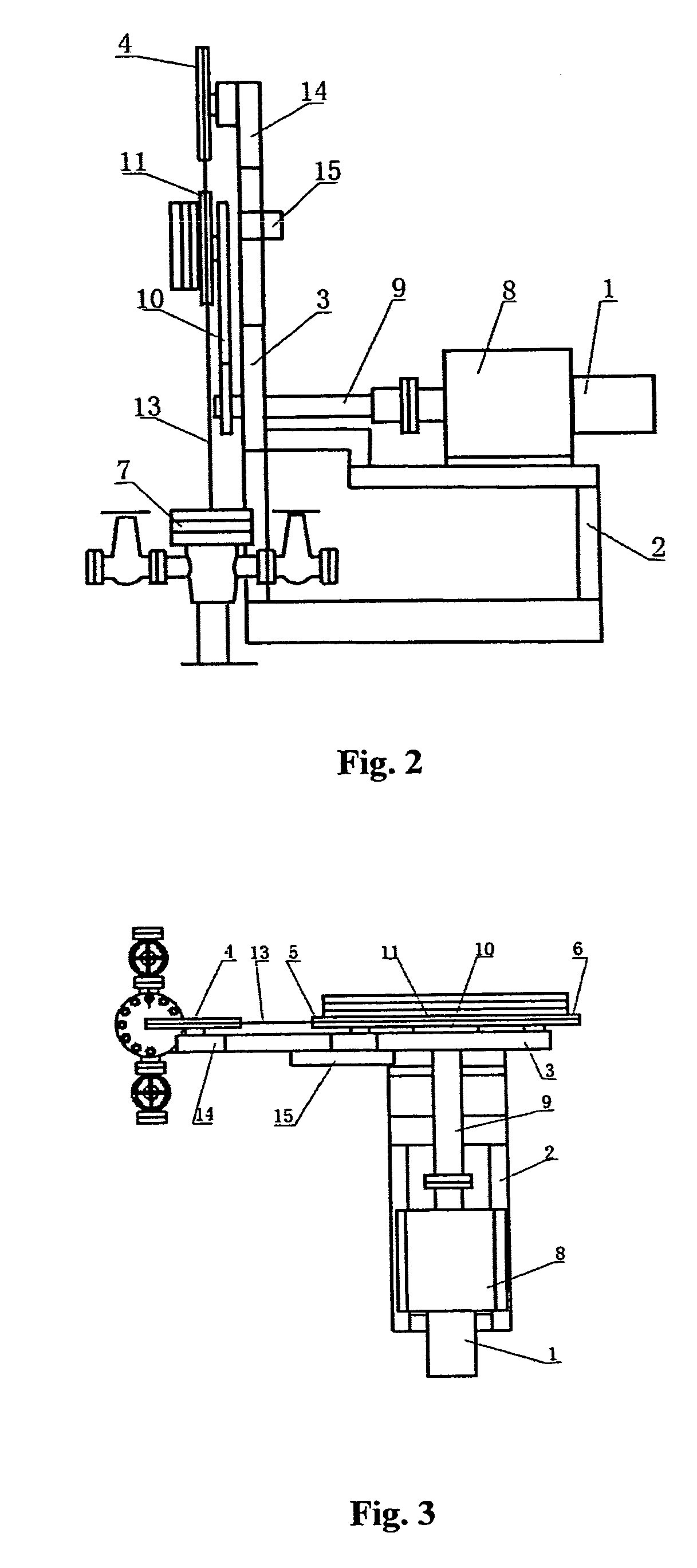
[0012]In the drawings and the following Description, the reference numerals identify the following elements of a pumping system in accordance with this invention: 1-electric motor; 2-pump basement or base unit; 3-support bracket; 4-fixed pulley; 5-fixed pulley; 6-fixed pulley; 7-flange; 8-speed reducer; 9-output shaft; 10-crank; 11-movable pulley; 12-top pump; 13-driving element or cable; 14-positioning bracket of positioning wheel; 15-brace; 16-tester; 17-bottom pumping unit; 18-oil tubing.

[0013]As shown in FIG. 1 in conjunction with FIGS. 2 and 3, the single-crank, double-stroke, flexible-cable pumping system of this invention comprises an electric motor 1, a pump basement or base unit 2, and a flange 7 attached or connected to the basement 2. The flange 7 is located between top and bottom flanges (not numbered) of a wellhead, and fixed to the wellhead for example with screws. A generally L-shaped support bracket 3 is vertically fixed onto a connection end of the basement 2 and al...


PUM


Abstract

A pumping system is described comprising a bracket being vertically fixed onto the connection end of a pump basement and also connected to a wellhead in order to support multiple fixed pulleys fixed on the same plane as the top end of the bracket), an electric motor and a speed reducer also successively being fixed to a lower end of the bracket. The end head of an output shaft of a speed reducer is connected by means of a crank whose top end head is connected with a movable pulley that is on the same plane as the fixed pulleys. A flexible cable vertically hung in the center of the wellhead is successively wound across the fixed pulleys and the movable pulley and then is locked onto the pump basement. The flexible cable is downwardly connected to a plunger element of an upper wellhead canned pump and also to a plunger element of a downhole oil well pump. This pumping system is characterized by good movement performance, high level of effective load factor, the ability to use the combination of its own driving power and special tools for complementing the characteristics of low power consumption on tripping the plunger of oil well pump, as well as relatively small dimension and low weight of the pumping system relative to conventional oilfield pumping units.

Description

CROSS-REFERENCE TO RELATED APPLICATIONS[0001]This application claims priority to Chinese patent application Ser. No. 2005-10116731.3 filed Oct. 28, 2005.FIELD OF THE INVENTION[0002]This invention relates generally to a lift or pumping system used, for example, in the field of oilfield production, and more particularly to an oilfield pumping apparatus.BACKGROUND OF THE INVENTION[0003]As the development of oilfield and related technologies has progressed, a wide variety of artificial lift or pumping equipment has become available. Such equipment ranges from the beam pumping unit to the submersible electric pump, screw pumps, and other specially designed devices in order to adapt to the equipment required for different production stages. Currently, the pumping unit most commonly used for artificial lift in oil production is the beam pumping unit. Based on the structural differences in the crank four-bar mechanisms of the horsehead, beam pumping units can be classified into conventional...

Claims


Application Information

Patent Timeline
Patent Type & Authority Patents(United States)
IPC IPC(8): E21B43/00E21B4/04F04B17/00
CPCF04B47/06
Inventor HAN, XIUTINGDONG, HUANZHONGZHANG, JIAMINWANG, SHUHUACHEN, FENGYOUMO, AIGUO
Owner PETROCHINA CO LTD
Why Eureka
Try Eureka