
System-on-chip power reduction through dynamic clock frequency

a technology of dynamic clock frequency and system on-chip power, applied in the direction of instruments, liquid/fluent solid measurement, generating/distributing signals, etc., can solve the problem of unnecessarily dissipating power, and achieve the effect of increasing a period of tim

Active Publication Date: 2009-12-29
MARVELL ASIA PTE LTD
View PDF9 Cites 25 Cited by
  • Summary
  • Abstract
  • Description
  • Claims
  • Application Information

AI Technical Summary

Benefits of technology

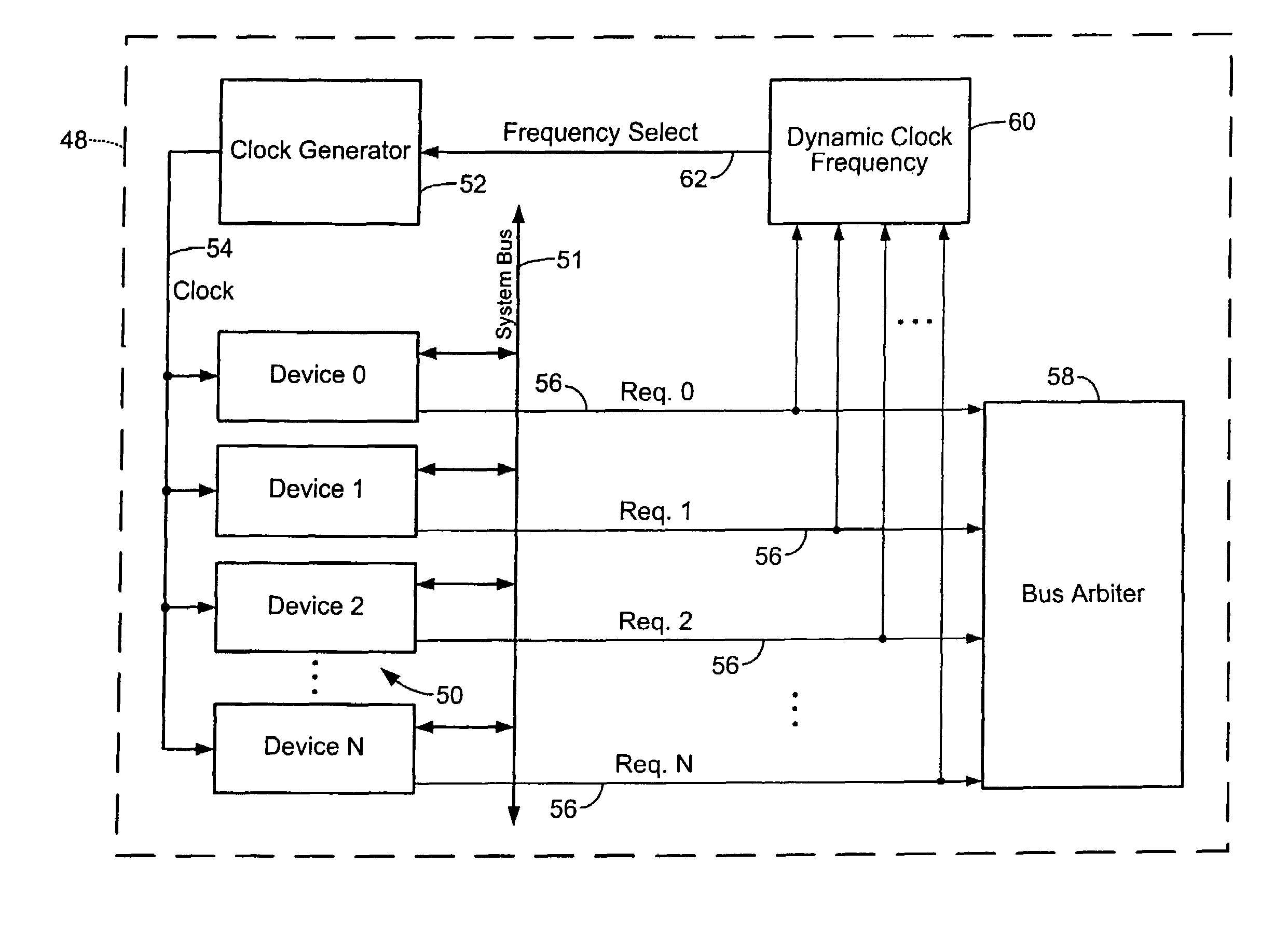
[0014]In other features, the request evaluation module includes a summing module that generates a sum of requests between the modules. A pulse stretch module communicates with the summing module and increases a period of time that at least one of the requests is asserted. The pulse stretch module increases the period of time based on the sum. The pulse stretch module increases the period of time to an estimated transaction duration.
[0015]In still other features of the invention, a low pass filter has an input that communicates with the summing module and an output that communicates with the frequency assignment module. The low pass filter prevents changes to the clock frequency value when the sum at least one of increases and decreases for less than a predetermined period. The low pass filter is one of a linear filter and a median filter. A slew rate control module communicates with the frequency assignment module and adjusts at least one of a rate of increase and a rate of decrease in the clock frequency value.

Problems solved by technology

However, in this case, power is unnecessarily dissipated when the data traffic in the SOC is lower.

Method used


Image

  • System-on-chip power reduction through dynamic clock frequency
  • System-on-chip power reduction through dynamic clock frequency
  • System-on-chip power reduction through dynamic clock frequency

Examples


Embodiment Construction

[0029]The following description of the preferred embodiment(s) is merely exemplary in nature and is in no way intended to limit the invention, its application, or uses. For purposes of clarity, the same reference numbers will be used in the drawings to identify similar elements. As used herein, the term module and / or device refers to an application specific integrated circuit (ASIC), an electronic circuit, a processor (shared, dedicated, or group) and memory that execute one or more software or firmware programs, a combinational logic circuit, and / or other suitable components that provide the described functionality.

[0030]Power dissipation in a system-on-chip (SOC) is minimized by minimizing the clock frequency of the system bus of the SOC. The clock frequency is dynamically changed according to the present invention based on the data traffic to reduce power consumption. Modules within the SOC assert request signals to request permission to use the system bus. The request signals ar...


PUM


Abstract

A dynamic clock frequency module for a system-on-chip (SOC) including modules that communicate over a system bus includes a request evaluation module that receives requests to utilize the system bus from the modules. A frequency assignment module calculates a clock frequency value for the system bus based on the requests received by the request evaluation module. The request evaluation module includes a summing module that generates a sum of requests between the modules. A pulse stretch module increases a period of time that at least one of the requests is asserted. A low pass filter prevents changes to the clock frequency value when the sum at least one of increases and decreases for less than a predetermined period. A slew rate control module adjusts at least one of a rate of increase and a rate of decrease in the clock frequency value.

Description

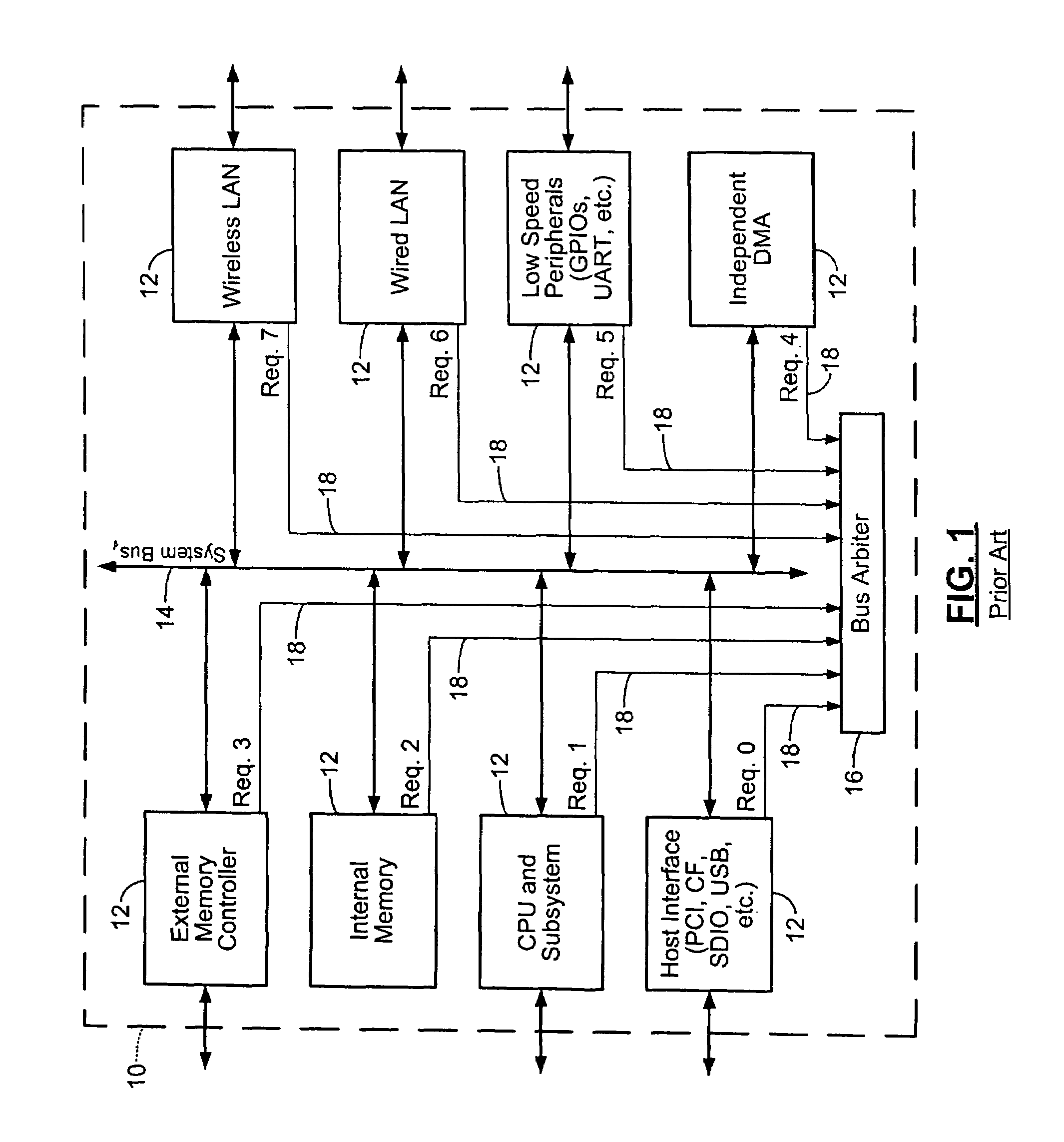
CROSS-REFERENCE TO RELATED APPLICATIONS[0001]This application claims the benefit of U.S. Provisional Application No. 60 / 506,797, filed on Sep. 29, 2003, and U.S. Provisional Application No. 60 / 551,876, filed on Mar. 10, 2004, which are both hereby incorporated by reference in their entirety.FIELD OF THE INVENTION[0002]The present invention relates to wireless network devices, and more particularly to reducing power dissipation in wireless network devices.BACKGROUND OF THE INVENTION[0003]Laptop computers, personal digital assistants (PDAs), and other mobile devices often incorporate wireless local area network (WLAN) technology that typically operates using battery power. Therefore, it is important to minimize power dissipation in mobile devices to preserve battery life. Sometimes WLAN circuits are implemented as a system-on-chip (SOC).[0004]Referring now to FIG. 1, an SOC 10 for a wireless network device includes modules 12 that communicate with each other over a system bus 14. The ...

Claims


Application Information

Patent Timeline
Patent Type & Authority Patents(United States)
IPC IPC(8): G06F1/32
CPCG06F1/08G06F1/324G06F1/3203Y02B60/1217Y02D10/00
Inventor DONOVAN, TIMOTHY
Owner MARVELL ASIA PTE LTD
Learn More