
Copper bonding or superfine wire with improved bonding and corrosion properties

a superfine wire and copper technology, applied in metal-working apparatus, solid-state devices, textiles and papermaking, etc., can solve the problems of loss of bonding capability, poor electrical and mechanical properties in comparison with copper or silver, undesirable hardness, etc., to improve the electrical and mechanical properties of copper, prolong the service life, and prolong the service li

Inactive Publication Date: 2010-01-12
HERAEUS PRECIOUS METALS GMBH & CO KG
View PDF14 Cites 31 Cited by
  • Summary
  • Abstract
  • Description
  • Claims
  • Application Information

AI Technical Summary

Benefits of technology

The invention relates to improving the bonding process of copper wires to silicon chips by adding a small amount of gold to the surface of the copper wire. This helps to prevent damage to the chip during bonding and also makes the wire easier to store and use. The use of a coated wire with a thin layer of gold or a copper-gold alloy eliminates the need for a hard FAB (fused alkaline bonding pad) and reduces the risk of chip damage during bonding. The bonding wire has good electrical and mechanical properties, can be made thinner, and is stable in storage. The surface treatment with gold can be done using conventional processes and the color of the copper wire can be made more distinct than that of the gold.

Problems solved by technology

Bonding and superfine wires usually consist of gold, although this has poorer electrical and mechanical properties in comparison with copper or silver.
The reason for this is the tarnishing property of copper, which loses its bonding capability in a short time.
However, this hardness is undesirable for bonding wires, since the semiconductor can be damaged by pressing the bonding or superfine wire onto the contact patches of the semiconductor.
Gold-copper alloys on copper wires can lead to cracks in the silicon chip during pressing onto the contact patches.

Method used


Image

  • Copper bonding or superfine wire with improved bonding and corrosion properties
  • Copper bonding or superfine wire with improved bonding and corrosion properties
  • Copper bonding or superfine wire with improved bonding and corrosion properties

Examples


example 1

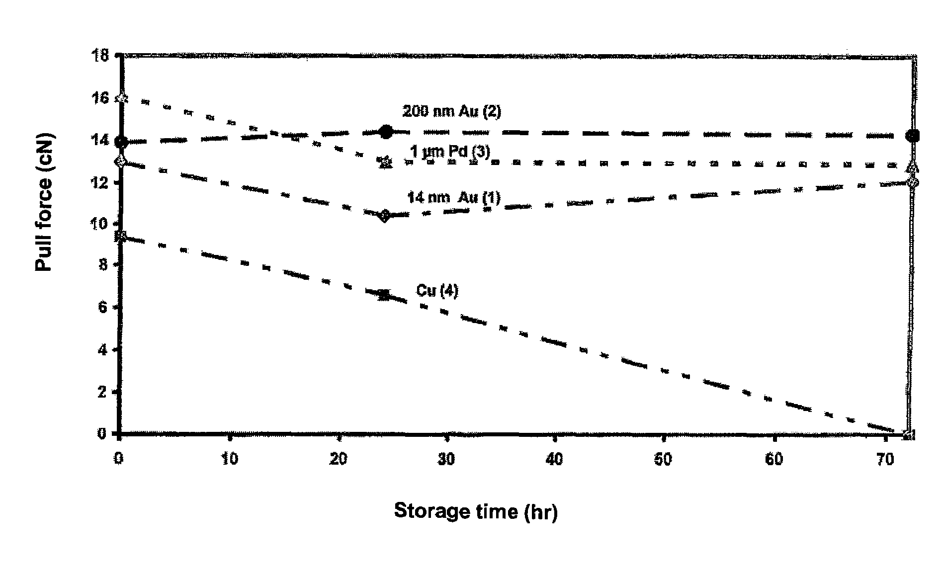
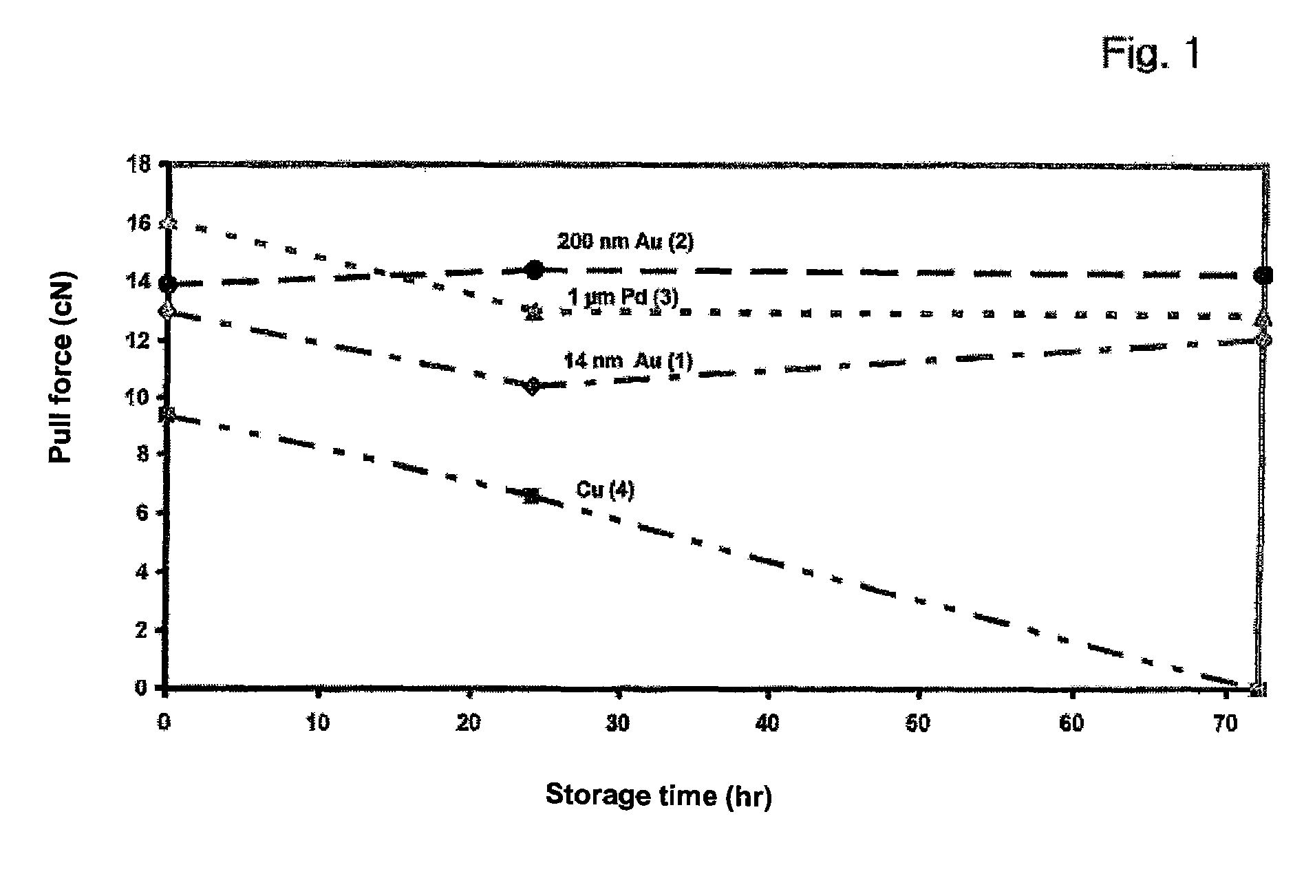
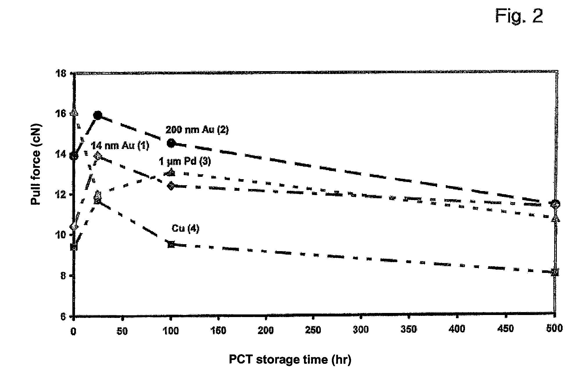
[0038]From FIGS. 1 and 2 it can be seen that a copper bonding or superfine wire according to an embodiment of the invention is corrosion stable with a 14 nm gold coating 1, and has a loop schear-off force comparable to bonding wires made of pure gold or pure copper. Thus, the bonding wires according to the invention are corrosion-stable relative to pure copper wires 4 and have an improved conductivity and improved stability relative to gold bonding wires. In an inventive manner, a choice was made between the possibilities of alloying or coating copper with gold, in which the increasing hardness of gold-copper alloys plays no role upon bonding, and therefore the chips 29 to be bonded are not damaged when pressing on the bonding or superfine wire.

[0039]The ball 21 provided for the bonding process remains soft, despite the corrosion protection, although gold-copper alloys are considered hard.

example 2

[0040]Cu-wire of 99.995% purity is electrolytically coated. The Cu-wire output diameter is 250 μm.

[0041]The Au-coated wires are pulled to 25 μm thickness by repeated pulling. In a subsequent pass-through annealing, the wires are set to a tearing load of 13 cN with a resulting breaking stretch of 14% (“soft condition”). To prevent oxidation of the freshly pulled wires, coils are vacuum-welded in PE film.

[0042]The wire used here would have a coating 20 nm thick, if the gold did not diffuse into the copper, or the copper into the gold. The diffusion obscures the phase boundary, so that a layer thickness can only be given for a fictitious jacketing, which is not real due to the diffusion. The wire obtained is copper-colored. Thus, when describing the invention, the designation gold-enriched surface is used instead of the expression gold jacketing or coating.

example 3

[0043]The above-mentioned bonding wires 20 are subjected to open storage and after a predetermined period of time undergo a bonding test per ASTM, 100 Barr Harbor Drive, West Conshohocken, Pa. 19428-2959 and G. G. Harman, “Wire Bonding in Microelectronics,” McGraw-Hill 1997, pp 67ff.

[0044]The bonding conditions are as follows:

[0045]Ball-wedge bonder (ESEC 3088) with the bonding parameters:

[0046]a) Ball side (impact 2000; force 3000; time 32; US 80) and

[0047]b) Wedge side (impact 300; force 1500; time 30; US 20)

The numeric specifications are bonder parameters.

[0048]As a substrate are used:

[0049]1. Gold-jacketed Cu—Sn6 substrate

[0050]2. Al-metallized Si chip

[0051]FIG. 1 shows the schear-off force resistance of the wire loops. The schear-off strength is determined using a pull tester (DAGE BT 22) and the so-called hook test MIL STD 883F, Jun. 18, 2004, Microcircuits, Method 2011.7.

[0052]The diagram in FIG. 1 shows a comparative storage resistance of a 14 nm Cu—BW 1 as a massive gold wi...


PUM

PropertyMeasurementUnit
diameteraaaaaaaaaa
thicknessaaaaaaaaaa
thicknessaaaaaaaaaa

Abstract

A bonding or superfine wire is provided made of copper, with a gold enrichment on the surface thereof, in particular in an amount corresponding to a coating of at most 50 nm. The wire may be bonded by the ball / wedge method, has a copper-colored appearance, and the ball thereof after flame-off has a hardness of less than 95 according to HV0.002. In order to produce the bonding or superfine wire, a copper wire is coated with gold or a copper-gold alloy or gold is introduced into the surface of the copper wire. The wires are bonded to a semiconductor silicon chip.

Description

CROSS-REFERENCE TO RELATED APPLICATIONS[0001]This application is a Continuation of International Application No. PCT / EP2006 / 001713, filed Feb. 24, 2006, which was published in the German language on Sep. 14, 2006, under International Publication No. WO 2006 / 094654 A1 and the disclosure of which is incorporated herein by reference.BACKGROUND OF THE INVENTION[0002]The present invention relates to a ball / wedge process in which a bonding or superfine wire made of copper is bonded to a semiconductor silicon chip; suitable superfine and bonding wires made of copper which are suitable for electrical connections for semiconductors; process for their manufacture and their use with semiconductors.[0003]According to G. G. Harman, “Wire Bonding in Microelectronics”, McGraw-Hill 1997, pp. 1-10, pp. 67ff and pp. 203ff, in the ball / wedge process the bonding or superfine wire is bonded to a chip using a flamed ball, which is also referred to as a free-air ball (FAB).[0004]Bonding wires are the conn...

Claims


Application Information

Patent Timeline
Patent Type & Authority Patents(United States)
IPC IPC(8): H01L23/49B32B15/02B21C1/00
CPCH01L24/45H01L2224/05624H01L2224/43825H01L2224/45015H01L2224/45147H01L2224/45565H01L2224/456H01L2224/45644H01L2224/45664H01L2224/45673H01L2224/48463H01L2224/85045H01L2224/85205H01L2224/859H01L2924/01005H01L2924/01006H01L2924/01013H01L2924/01014H01L2924/01029H01L2924/01033H01L2924/01046H01L2924/01047H01L2924/0105H01L2924/01079H01L2924/01082H01L2924/01204H01L2924/10253H01L2924/14H01L2924/19042H01L2924/20752H01L2924/01019H01L2924/01068H01L2924/014H01L2224/45144H01L2224/45164Y10S428/941H01L2224/48624Y10T428/12458Y10T428/2938Y10T428/12438Y10T428/12431H01L2924/00014H01L2924/00011H01L2924/00H01L2224/48824H01L2924/00015H01L2224/45139H01L24/85H01L2224/43848H01L24/48H01L2924/20755H01L2924/2075H01L2924/2076H01L2924/20754H01L2924/01049H01L23/49H01L23/48
Inventor BISCHOFF, ALBRECHTFORDERER, HEINZSCHRAPLER, LUTZKRUGER, FRANK
Owner HERAEUS PRECIOUS METALS GMBH & CO KG
Learn More