
Method and apparatus for attaching connective tissues to bone using a cortical bone anchoring device

a technology of cortical bone and anchoring device, which is applied in the field of anchoring methods and methods for securing connective tissue, can solve the problems of increasing the common problem of tendons, pain and loss of the ability to elevate and externally rotate the arm, and residual weakness

Inactive Publication Date: 2010-03-09
ARTHROCARE
View PDF340 Cites 59 Cited by
  • Summary
  • Abstract
  • Description
  • Claims
  • Application Information

AI Technical Summary

Benefits of technology

[0022]The present invention overcomes the disadvantages of prior art devices and provides further advantages by utilizing the difference in density in the cortical bone (the tough, dense outer layer of bone) and the cancellous bone (the less dense, airy and somewhat vascular interior of the bone). There is a clear demarcation between the cortical bone and cancellous bone, where the cortical bone presents a kind of hard shell over the less dense cancellous bone.
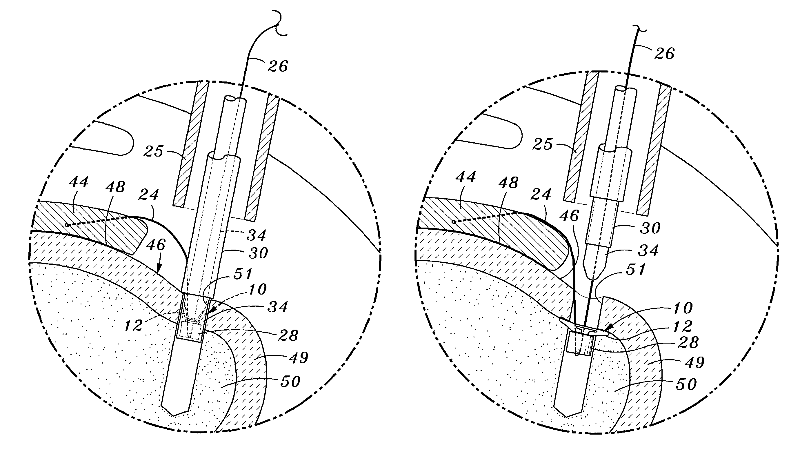
[0023]A major aspect of the present invention is to provide a means to either attach a suture securing device to the inventive anchoring device, or to attach a suture directly to the inventive device outside the body, then deploy the entire apparatus into the procedural area through a lumen in a tube. Once inserted into the procedural area within the bone, the device is expanded to anchor it beneath the cortical layer of bone. When the device is deployed, it extends radially into the cancellous bone just beneath the cortical layer of bone at the point at which the cortical and cancellous layers of bone meet. The manner in which the present invention is designed prevents it from returning, after it has been deployed, to the folded or bent profile it assumed as it was being deployed. This design, moreover, prevents the invention from moving proximally due to the density of the cortical bone against which it is seated, or from moving either distally or radially due to the amount of anchor surface area which is extended into the cancellous bone. This approach is practicable for use in an arthroscopic procedure and eliminates the disadvantages associated with the use of screws, tacks, and staples described above. The present invention solves the problems outlined above by providing innovative bone anchor and connective techniques which permit a suture attachment which lies beneath the cortical bone surface, without the necessity of tying knots.

Problems solved by technology

It is an increasingly common problem for tendons and other soft, connective tissues to tear or to detach from associated bone.
One such type of tear or detachment is a “rotator cuff” tear, wherein the supraspinatus tendon separates from the humerus, causing pain and loss of ability to elevate and externally rotate the arm.
Because of this maneuver, the deltoid requires postoperative protection, thus retarding rehabilitation and possibly resulting in residual weakness.
Although the above described surgical techniques are the current standard of care for rotator cuff repair, they are associated with a great deal of patient discomfort and a lengthy recovery time, ranging from at least four months to one year or more.
It is the above described manipulation of the deltoid muscle together with the large skin incision that causes the majority of patient discomfort and an increased recovery time.
Unfortunately, the skill level required to facilitate an entirely arthroscopic repair of the rotator cuff is inordinately high.
Intracorporeal suturing is clumsy and time consuming, and only the simplest stitch patterns can be utilized.
Extracorporeal knot tying is somewhat less difficult, but the tightness of the knots is difficult to judge, and the tension cannot later be adjusted.
So, knots tied arthroscopically are difficult to achieve, impossible to adjust, and are located in less than optimal areas of the shoulder.
Suture tension is also impossible to measure and adjust once the knot has been fixed.
Consequently, because of the technical difficulty of the procedure, presently less than 1% of all rotator cuff procedures are of the arthroscopic type, and are considered investigational in nature.
Another significant difficulty with current arthroscopic rotator cuff repair techniques are shortcomings related to currently available suture anchors.
Suture eyelets in bone anchors available today, which like the eye of a needle are threaded with the thread or suture, are small in radius, and can cause the suture to fail at the eyelet when the anchor is placed under high tensile loads.
Screws are known for creating such attachments, but suffer from a number of disadvantages, including their tendency to loosen over time, requiring a second procedure to later remove them, and their requirement for a relatively flat attachment geometry.
These anchors still suffer from the aforementioned problem of eyelet design that stresses the sutures.
Other methods of securing soft tissue to bone are known in the prior art, but are not presently considered to be feasible for shoulder repair procedures, because of physicians' reluctance to leave anything but a suture in the capsule area of the shoulder.
The reason for this is that staples, tacks, and the like could possibly fall out and cause injury during movement.
Also, the tacks or staples require a substantial hole in the soft tissue, and make it difficult for the surgeon to precisely locate the soft tissue relative to the bone.
This method presents the same disadvantage with respect to the amount of surface area in contact with the bone as described in connection with the Harwin, et. al. patent, supra.
This approach, however, suffers the disadvantage of a small surface area disposed against the bone and a relatively weak construction and resultant anchoring interface.
These anchors, however, do not have the ability to be bent or flexed for deployment through a narrow lumen or hypotube, making insertion and placement difficult.
They also suffer from the same disadvantage of a small surface area to be disposed against the cortical bone as the other applications described above.
This anchor also has a relatively limited surface area contact with the lower surface of the cortical bone and with the surrounding cancellous bone, and can be difficult and tricky to insert and deploy.

Method used


Image

  • Method and apparatus for attaching connective tissues to bone using a cortical bone anchoring device
  • Method and apparatus for attaching connective tissues to bone using a cortical bone anchoring device
  • Method and apparatus for attaching connective tissues to bone using a cortical bone anchoring device

Examples


Embodiment Construction

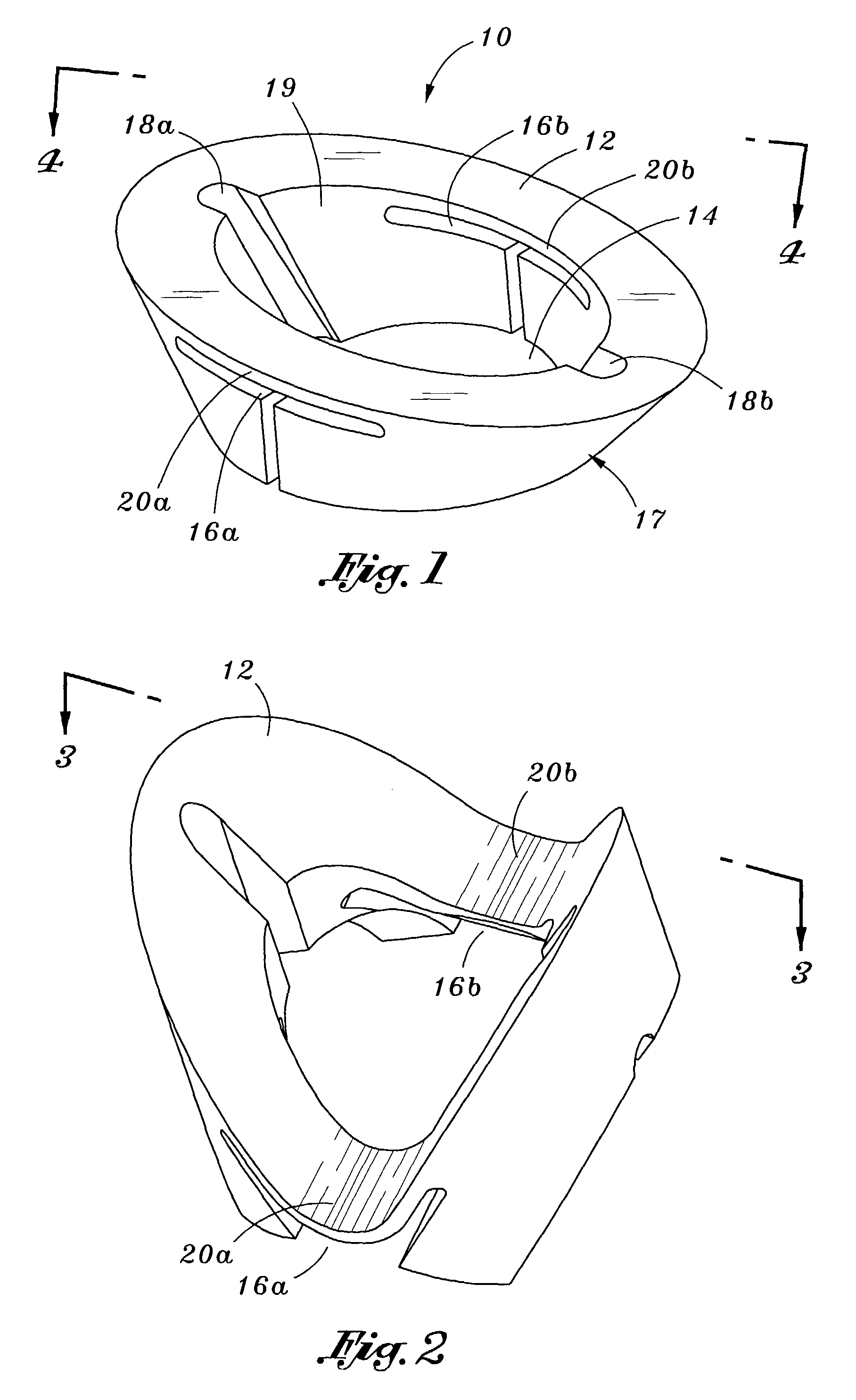
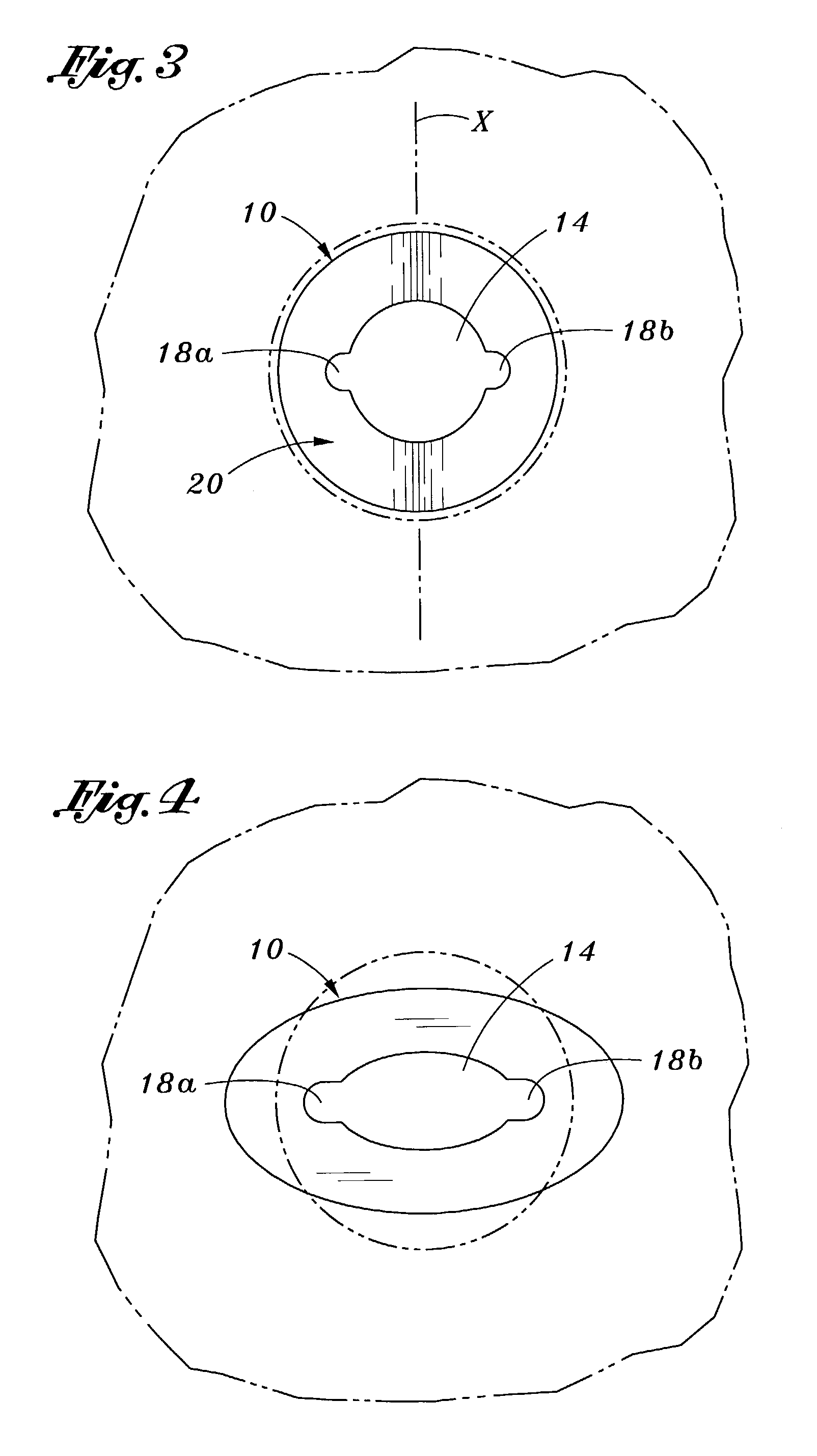
[0055]Referring now more particularly to the drawings, there is shown in FIG. 1 a bone anchor 10 constructed in accordance with an embodiment of the present invention, comprised of an elliptical disk 12 with a generally circular aperture 14 in its center. In this first embodiment, the disk 12 is fabricated of flat stock, preferably 301 stainless spring steel, or other biocompatible equivalent material, and has a thickness of approximately 0.031 inches. First and second slits 16a and 16b, respectively, formed in a generally “T” shape when viewed from the side, are cut into each side of the annular disk from its distal end, using electro-discharge machining (EDM) techniques, or the like, and are spaced approximately 180 degrees from each other about the periphery of the disk. The “T” shaped slits 16a, b are cut entirely through the annular sidewall 17 of the disk 12, and function to allow the disk to be bent in an upward or proximal direction for deployment into a portion of bone, as ...


PUM


Abstract

A bone anchor device for attaching connective tissue to bone comprises a disk adapted for insertion into a portion of bone to which the connective tissue is to be attached. The disk is movable between a bent orientation for presenting a smaller cross-section and an expanded orientation for presenting a larger cross-section. The bent orientation is utilized for inserting the disk through a small hole into a region of cancellous bone beneath the cortical bone layer, after which the disk is actuated to its expanded orientation so that it will be permanently anchored in the cancellous bone, as it will be too large to return proximally through the hole in the cortical bone layer. Two embodiments are disclosed. In a first embodiment, the disk is initially formed in the expanded orientation, of spring steel. In a second embodiment, the disk is initially formed in the bent orientation, and spring steel is not required.

Description

[0001]This application is a continuation of application Ser. No. 09 / 876,260, filed on Jun. 6, 2001, and now U.S. Pat. No. 6,547,800, which application is herein expressly incorporated by reference.BACKGROUND OF THE INVENTION[0002]This invention relates generally to methods and apparatus for attaching soft tissue to bone, and more particularly to anchors and methods for securing connective tissue, such as ligaments or tendons, to bone. The invention has particular application to arthroscopic surgical techniques for reattaching the rotator cuff to the humeral head, in order to repair the rotator cuff.[0003]It is an increasingly common problem for tendons and other soft, connective tissues to tear or to detach from associated bone. One such type of tear or detachment is a “rotator cuff” tear, wherein the supraspinatus tendon separates from the humerus, causing pain and loss of ability to elevate and externally rotate the arm. Complete separation can occur if the shoulder is subjected t...

Claims


Application Information

Patent Timeline
IPC IPC(8): A61B17/04A61B17/58A61F2/28
CPCA61B17/0401A61F2/0811A61B2017/0409A61B2017/0414A61B2017/0458A61F2/0805A61F2002/0835A61F2002/0864A61F2002/0888A61B17/56
Inventor FOERSTER, SETH A.GORDON, NORMAN S.
Owner ARTHROCARE
Learn More