Assembly for transmitting information via a low-voltage power supply network

network technology, applied in the field of arrangement for transmitting information via a low-voltage power supply system, can solve the problems of reducing the data rate, affecting the quality of the message transmission, and often preventing interference at the receiver, so as to prevent interference signals, prevent radio-frequency interference, and improve the effect of transmission quality

Inactive Publication Date: 2010-03-09
CURRENT COMMUNICATIONS INTERNATIONAL HOLDING GMBH
View PDF30 Cites 12 Cited by
  • Summary
  • Abstract
  • Description
  • Claims
  • Application Information

AI Technical Summary

Benefits of technology

[0024]As already mentioned, most appliances which are connected to the low-voltage power supply system produce radio-frequency interference signals, which are superimposed on a radio-frequency transmission signal and can have a negative effect on data transmission. Data terminals are no exception to this. However, in order to prevent the interference signals from the data terminal interfering with the transmission of its own messages, an induction coil is located in each mains link, that is to say between each mains connection and appliance connection. These induction coils filter radio-frequency signal elements out of the signals transmitted via the corresponding conductors, and in this way keep radio-frequency interference away from the power supply system.
[0025]However, the induction coils have another major advantage. They prevent parts of the radio-frequency transmission signal from reaching the data terminal via the appliance connection of the coupling apparatus. They thus ensure that, firstly, no radio-frequency signals can enter the data terminal as virtual interference signals via the power supply connection and, secondly, that the transmission signal passes from the low-voltage power supply system to the transmitting / receiving apparatus, and from the transmitting / receiving apparatus to the low-voltage power supply system, with as little power loss as possible.
[0026]The coupling apparatus according to the invention is preferably used in low-voltage power supply systems with a system frequency of less than 1 kHz. The frequency of the carrier signal onto which the messages are modulated is between 1 MHz and 60 MHz. In order to suppress the undesirable interference optimally in such conditions, the induction coils in the mains conductor connections preferably each have an inductance of between 1 μH and 20 μH. The use of induction coils saves space and avoids saturation effects.

Problems solved by technology

Various processes can result in radio-frequency interference occurring in low-voltage power supply systems, which interference is superimposed on the carrier signal and is also output with it and, in some circumstances, has a disadvantageous influence on the quality of the message transmission.
In consequence, it is necessary to repeat transmissions, and this results in a reduction in the data rate.
Suppression of such interference at the receiver is often feasible only with a considerable amount of circuitry complexity, or is entirely impossible.

Method used


Image

  • Assembly for transmitting information via a low-voltage power supply network
  • Assembly for transmitting information via a low-voltage power supply network
  • Assembly for transmitting information via a low-voltage power supply network

Examples


Embodiment Construction

[0008]The object of the invention is to specify an arrangement of the type mentioned initially, which avoids the problems that occur with the prior art and whose suitability for transmitting messages is considerably improved, and to specify a coupling apparatus which is suitable for use in the arrangement according to the invention.

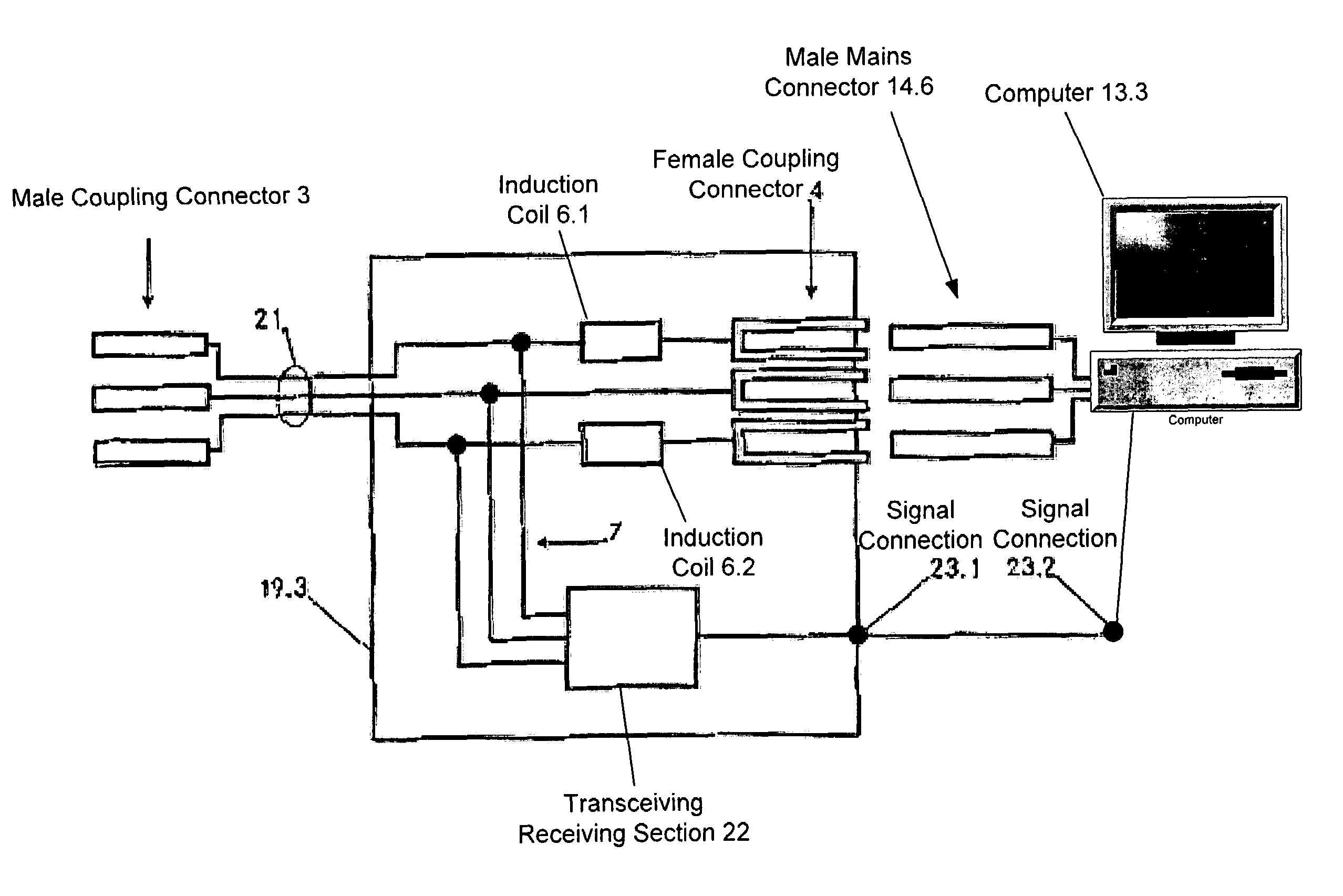
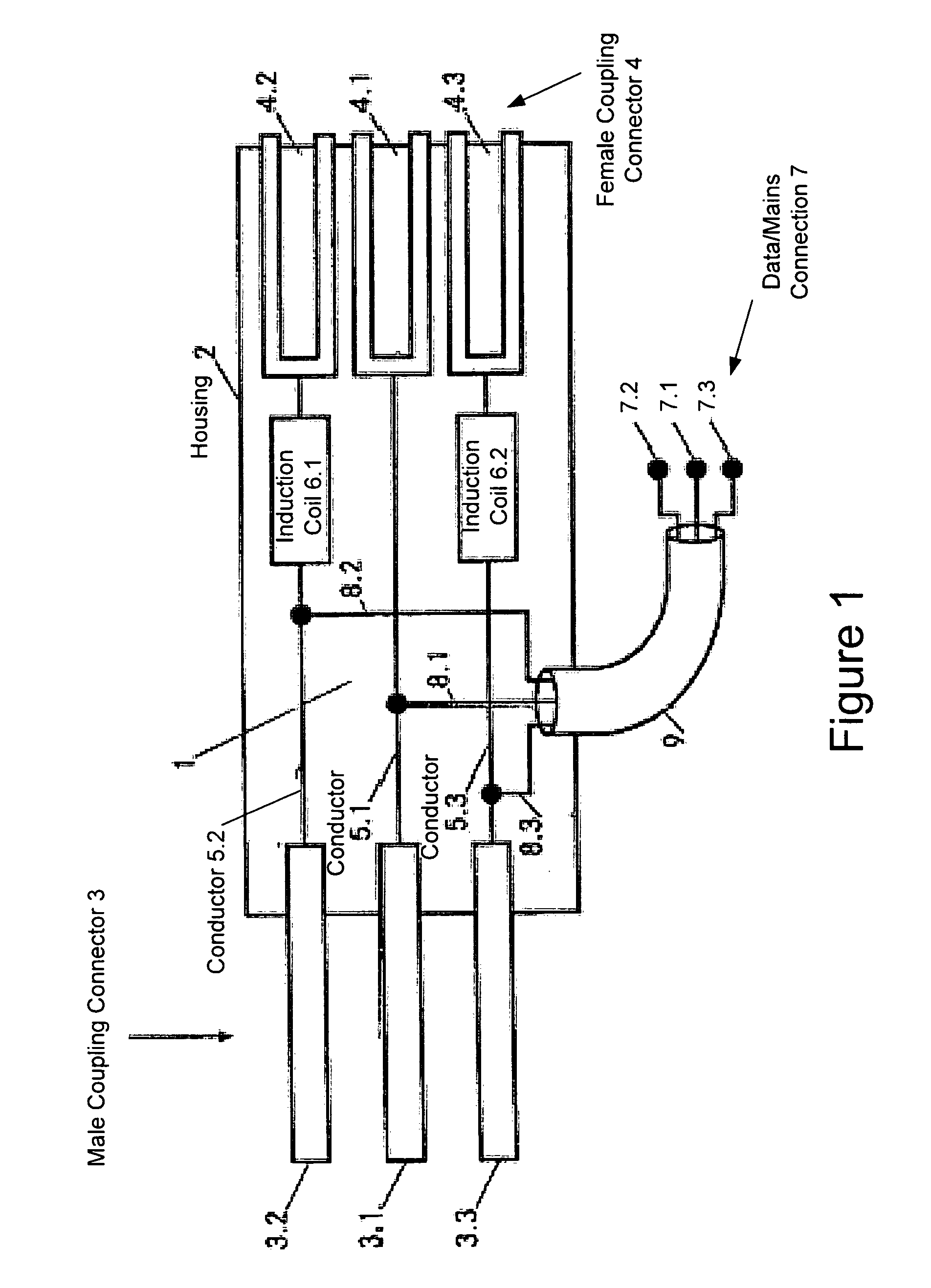
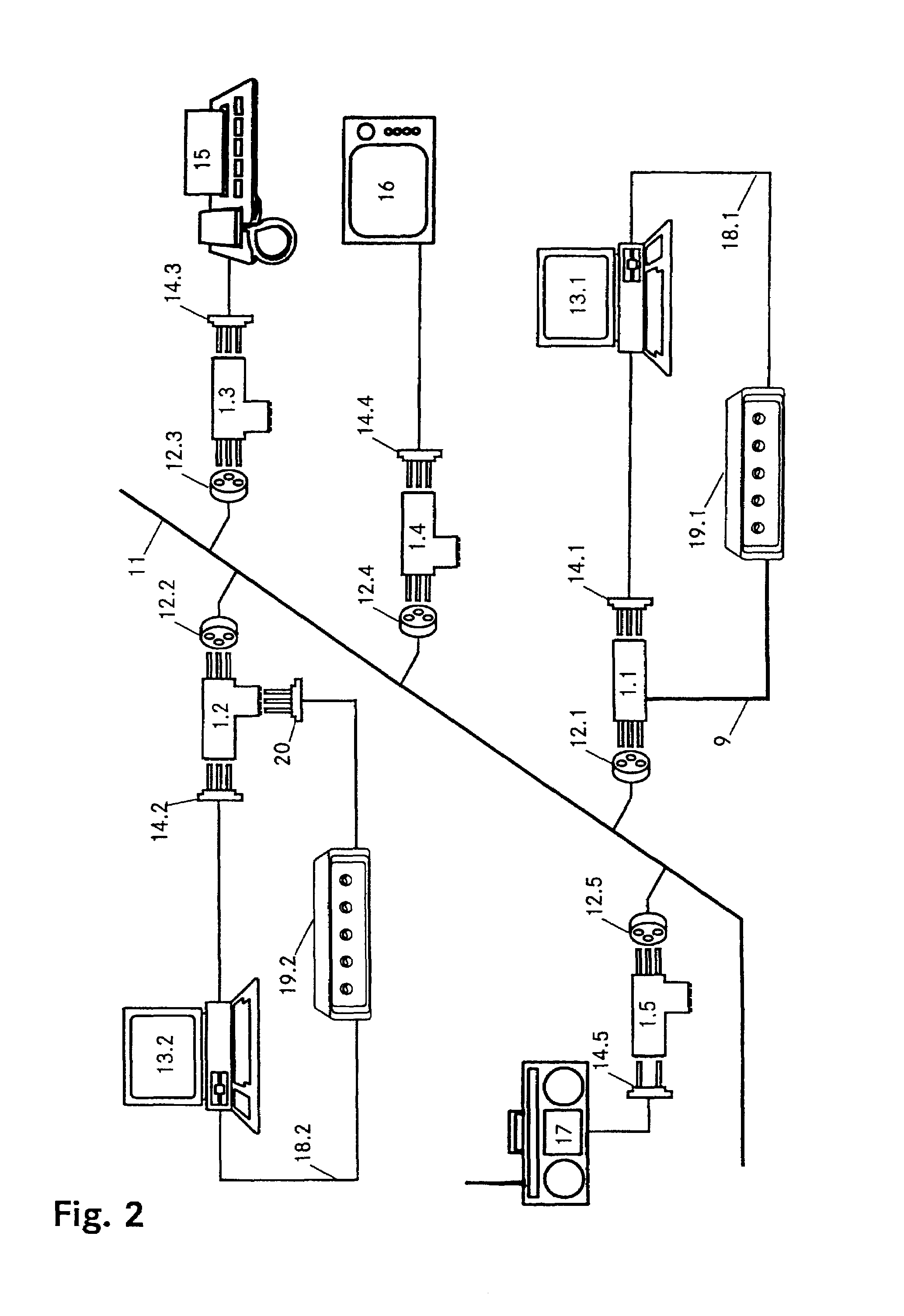
[0009]The solution of the object is defined by the features in claim 1. According to the invention, the arrangement for transmitting messages via a low-voltage power supply system comprises a first and a second data terminal between which the messages are transmitted, with the first data terminal being connected to the low-voltage power supply system via at least one coupling apparatus. For this purpose, apart from a mains connection for connection of the coupling apparatus to the low-voltage power supply system and an appliance connection for connection of an appliance to be supplied with electrical power to the coupling apparatus, each coupling apparatu...


PUM


Abstract

A coupling apparatus for facilitating communications of data signals over a low voltage electric power network is provided. In one embodiment, the apparatus includes a mains terminal configured to be connected to a low voltage electric power network carrying alternating current (AC) power and an appliance terminal configured to receive a male electric plug. The two terminals may be housed in a housing and connected via one or more inductive elements that attenuate high frequencies while allowing the AC power to pass through substantially unimpeded. Thus, interference caused by an appliance connected to the appliance terminal is filtered to prevent such interference from being conducted onto the low voltage electric power network. The apparatus also may include a third terminal that in some embodiments is electrically connected to the mains terminal to thereby output the data signals and AC power. In other embodiments, a modem may connect the third terminal to the mains terminal in which case the third terminal may communicate demodulated data to a communication device without outputting the AC power.

Description

[0001]This application is the national phase under 35 U.S.C. §371 of PCT International Application No. PCT / CH99 / 00592 which has an International filing date of Dec. 8, 1999, which designated the United States of America.TECHNICAL FIELD[0002]The invention relates to an arrangement for transmitting messages via a low-voltage power supply system, comprising a first and a second data terminal, and a coupling apparatus.PRIOR ART[0003]Electronic communications, that is to say the transmission of data in electronic form, is becoming increasingly important. This relates not only to supplying a bank specialist with the latest stock market data directly to his work station, but also to switching on the heating at home by remote control while travelling back from a winter holiday. The appropriate data are normally generated and processed in data terminals such as computers, which are connected to the power supply system to supply them with electrical power.[0004]One possible transportation rou...

Claims


Application Information

Patent Timeline
Patent Type & Authority Patents(United States)
IPC IPC(8): H02J3/02H01R13/719H04B3/56H04L12/28
CPCH01R13/719H04B3/56H04B2203/5437H04B2203/5445H04B2203/545H04B2203/5483
Inventor MULLER, KURTWIDMER, HANSPETER
Owner CURRENT COMMUNICATIONS INTERNATIONAL HOLDING GMBH
Why Eureka
Try Eureka