Device for automatically detecting remainders in aerospace engine

An automatic detection device and aerospace engine technology, which is applied in the direction of analyzing materials and instruments, can solve the problems of unstable operation, mechanical impact interference, and low detection efficiency, so as to reduce labor intensity, avoid interference signals, and achieve stability Effect

Inactive Publication Date: 2014-04-02
HARBIN INST OF TECH
View PDF3 Cites 3 Cited by
  • Summary
  • Abstract
  • Description
  • Claims
  • Application Information

AI Technical Summary

Problems solved by technology

[0005] The purpose of the present invention is to solve the problems of low detection efficiency, poor detection accuracy, and unstable operation state caused by mechanical impact interference during the shaking or shaking process of the traditional redundant object detection method of aerospace engines, and provides an automatic detection device for redundant objects of aerospace engines

Method used


Image

  • Device for automatically detecting remainders in aerospace engine
  • Device for automatically detecting remainders in aerospace engine
  • Device for automatically detecting remainders in aerospace engine

Examples


specific Embodiment approach 1

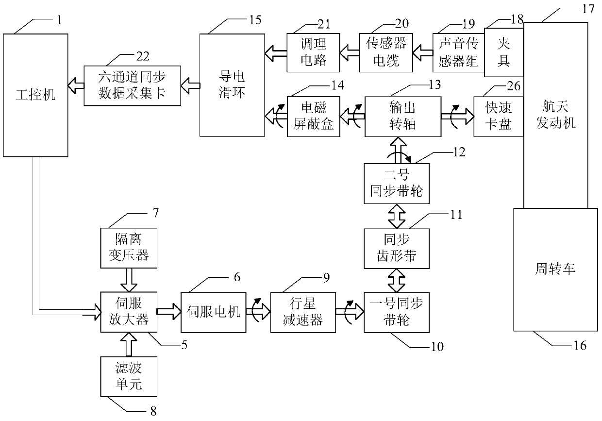
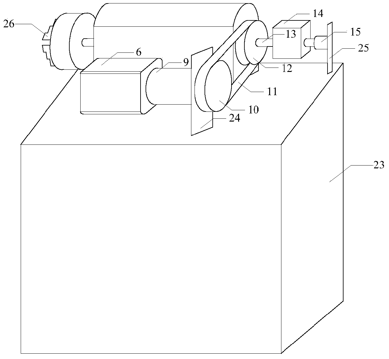
[0027] Specific implementation mode one: the following combination figure 1 , image 3 and Figure 10 Describe this embodiment, a kind of aerospace engine excess automatic detection device described in this embodiment, it comprises industrial computer 1, servo amplifier 5, servo motor 6, planetary reducer 9, No. 1 synchronous pulley 10, synchronous toothed belt 11. No. 2 synchronous pulley 12, output shaft 13, electromagnetic shielding box 14, conductive slip ring 15, turnover car 16, fixture 18, sound sensor group 19, sensor cable 20, conditioning circuit 21, six-channel synchronous data acquisition card 22 and quick chuck 26;

[0028] The control signal output terminal of the industrial computer 1 is connected with the input terminal of the servo amplifier 5;

[0029] The output end of the servo amplifier 5 is connected with the drive end of the servo motor 6;

[0030] The output shaft of the servo motor 6 is connected to the input shaft of the planetary reducer 9, and t...

specific Embodiment approach 2

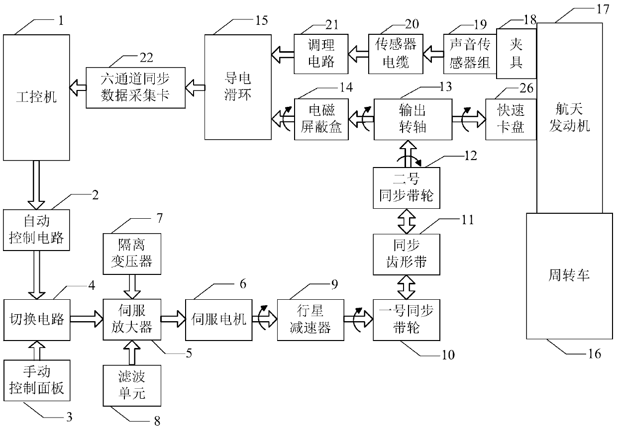
[0041] Specific implementation mode two: the following combination figure 2 and image 3 Describe this embodiment mode, this embodiment mode will further explain embodiment one, it also includes automatic control circuit 2, manual control panel 3 and switching circuit 4;

[0042] The control signal output end of the industrial computer 1 is connected with the input end of the automatic control circuit 2;

[0043] The output end of the automatic control circuit 2 is connected with the automatic control signal input end of the switching circuit 4;

[0044] The output terminal of the manual control panel 3 is connected with the manual control signal input terminal of the switching circuit 4;

[0045] The output terminal of the switching circuit 4 is connected with the input terminal of the servo amplifier 5 .

[0046]The servo system has two control modes: manual control and automatic control. When the servo system works in the automatic control mode, the industrial computer ...

specific Embodiment approach 3

[0052] Embodiment 3: This embodiment further describes Embodiment 1 or 2. It also includes an isolation transformer 7 , and the isolation transformer 7 is arranged between the output end of the power supply line and the input end of the servo amplifier 5 .

[0053] Isolation transformer 7: When the servo amplifier 5 and the servo motor 6 are working, a large amount of high-frequency electromagnetic interference will be generated. Since the servo system and the detection system are at the same grid point, the high-frequency interference of the servo system may flow back to the power supply and ground wire of the grid, causing interference to the detection equipment. The 380V power supply line is used to supply power to the servo system separately after passing through the three-phase isolation transformer, so that the servo system and the detection system do not have electrical contact, thereby effectively isolating.


PUM


Abstract

The invention relates to a device for automatically detecting remainders in an aerospace engine, and belongs to the technical field of detecting the remainders in the aerospace engine. The device aims to solve the problem of low detecting efficiency in the traditional remainder detecting method during swinging or swaying in the aerospace engine. A detecting device which is arranged on a turn table comprises an industrial personal computer, a servo amplifier, a servo motor, a planetary reducer, a No. 1 synchronous pulley, a synchronous cog belt, a No. 2 synchronous pulley, an output rotating shaft, an electromagnetic shielding box, a conducting slip ring, a tote cart, a clamp, an acoustic sensor group, a sensor cable, a conditioning circuit, a six-channel synchronous data acquisition card and a fast chuck, wherein the aerospace engine is arranged on the tote cart; the industrial personal computer controls the servo motor to drive the output rotating shaft to rotate, the fast chuck for mounting and clamping the aerospace engine is mounted at one end of the output rotating shaft, and the electromagnetic shielding box and the rotor part of the conducting slip ring is mounted at the other end of the output rotating shaft; the detection signal of the acoustic sensor group is fed back to the industrial personal computer.

Description

technical field [0001] The invention relates to an automatic detection device for redundant objects of aerospace engines, which belongs to the technical field of detection of redundant objects inside aerospace engines. Background technique [0002] As the main propulsion device of missiles, launch vehicles and spacecraft, the reliability of aerospace engines directly determines the operating life and performance of aerospace systems. The production and manufacturing of the engine includes many process steps. In the process of welding, assembly and other processes, it is unavoidable to introduce various particles into the product, and finally seal them in the product to form redundant matter. The aerospace engine is often under the condition of ultra-high acceleration or severe impact during the working process, and the movement process of the excess has great randomness, or it is suspended in the cavity, or falls on some contact parts, which has a great impact on the reliabi...

Claims


Application Information

Patent Timeline
Patent Type & Authority Applications(China)
IPC IPC(8): G01N35/00
Inventor 翟国富陈金豹戚乐赵国强郭亮李超牛鹏飞梁安生钱鑫邓智王伟城
Owner HARBIN INST OF TECH
Why Eureka
Try Eureka