
Alunite type compound particles, manufacturing process thereof and use thereof

a technology of compound particles and manufacturing processes, applied in the field of alunite type compound particles, can solve the problems of difficult to control the shape of each particle, large variation in particle size, incomplete methods, etc., and achieve the effects of low cost, high reproducibility, and high yield

Inactive Publication Date: 2010-03-16
KYOWA CHEM IND
View PDF9 Cites 4 Cited by
  • Summary
  • Abstract
  • Description
  • Claims
  • Application Information

AI Technical Summary

Benefits of technology

The resulting particles exhibit high dispersibility, low moisture absorptivity, and acid resistance, maintaining mechanical properties and performance even at high densities, making them suitable for various industrial applications.

Problems solved by technology

However, it is extremely difficult to control the shape of each particle, and additive particles which are uniform in shape and size have not been proposed up till now.
This method is incomplete and also unpractical and uneconomical because the alkali hydroxide must be added as a pH controller to stabilize the shape of each particle while pH is measured at certain time intervals during the reaction.
Thus, the particles greatly vary in size and cannot meet the above requirements for resin additives.
For the recent measurement of average particle diameter and particle size distribution of fine particles, the laser diffraction method is becoming popular, and the Coulter method is not suitable for the measurement of fine particles having an average particle diameter of 0.5 μm or less, particularly 0.2 μm or less.

Method used


Image

  • Alunite type compound particles, manufacturing process thereof and use thereof
  • Alunite type compound particles, manufacturing process thereof and use thereof
  • Alunite type compound particles, manufacturing process thereof and use thereof

Examples


example 1

Synthesis of Alunite Type Compound Particles

example 1-a

Synthesis of Na0.96Al3(SO4)1.92(OH)6.12.0.63H2O

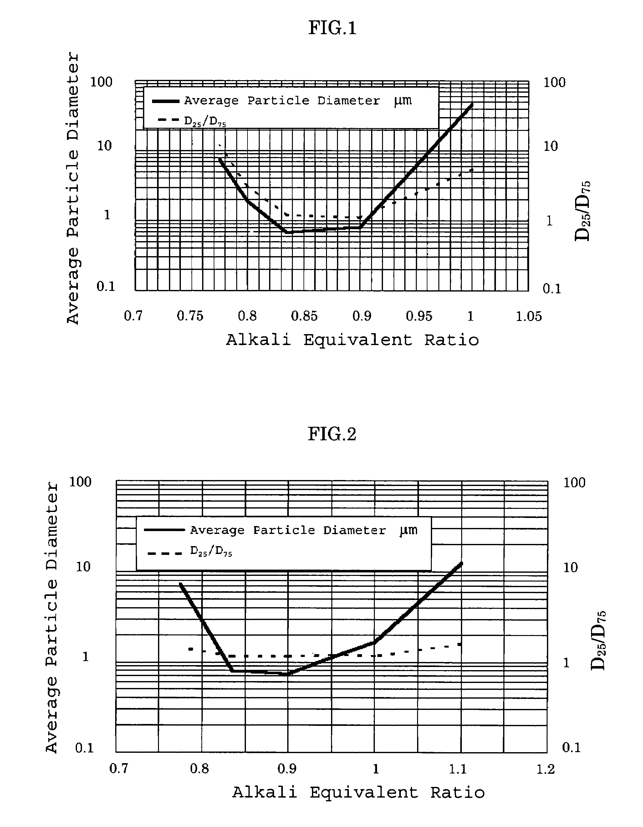
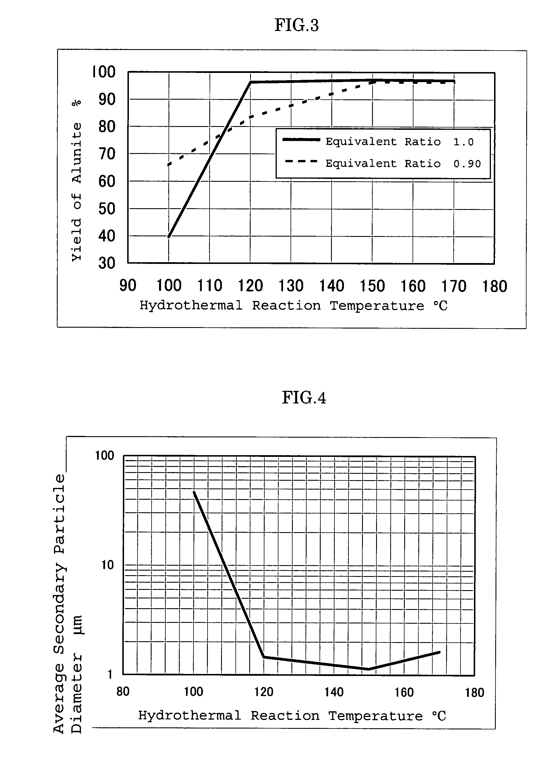
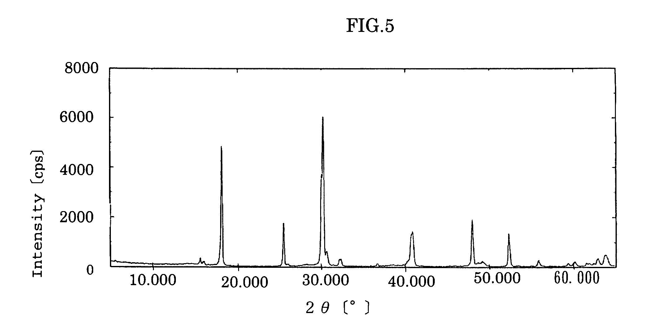
[0143]127 ml of an aqueous solution of aluminum sulfate having a concentration of 1.025 mol / l and 18.46 g (0.13 mol) of sodium sulfate were added to deionized water to prepare 500 ml of a solution, and 154 ml of 3.382 N sodium hydroxide solution was injected into the above solution under agitation at room temperature over about 1 minute (alkali equivalent ratio: 1.0). After another 20 minutes of agitation, the resulting solution was transferred to an autoclave to carry out a hydrothermal reaction at 170° C. for 2 hours. The reaction solution was cooled to 25° C., filtered, rinsed with 500 ml of water and dried at 105° C. for 22 hours to obtain spherical alunite type compound particles. The characteristic properties of the obtained alunite type compound particles are shown in Table 1. An X-ray diffraction image of the particles is shown in FIG. 5.

example 1-b

Synthesis of Na1.12Al3(SO4)2.17(OH)5.78.0.94H2O

[0144]Alunite type compound particles were synthesized in the same manner as in Example 1-A except that the alkali equivalent ratio was changed to 0.95. The results are shown in Table 1.


PUM

PropertyMeasurementUnit
average secondary particle diameteraaaaaaaaaa
particle size distributionaaaaaaaaaa

Abstract

Alunite type compound particles represented by the following general formula (I) and having a specific value of D75 / D25 when D25 is the particle diameter of particles which account for 25% of the total and D75 is the particle diameter of particles which account for 75% of the total in the cumulative particle size distribution curve measured by a laser diffraction method:Ma[Al1-xM′x]3(SO42−)y(OH)z.mH2O  (I)wherein M is at least one cation selected from the group consisting of Na+, K+, NH4+ and H3O+, M′ is at least one cation selected from the group consisting of Cu2+, Zn2+, Ni2+, Sn4+, Zr4+ and Ti4+, and a, m, x, y and z satisfy 0.8≦a≦1.35, 0≦m≦5, 0≦x≦0.4, 1.7≦y≦2.5, and 4≦z≦7, respectively. The above particles of the present invention have a small average particle diameter, are spherical, disk-like or hexagonal and have an extremely narrow particle size distribution.

Description

TECHNICAL FIELD[0001]The present invention relates to alunite type compound particles, a manufacturing process thereof and use thereof. That is, it relates to alunite type compound particles which can be used in a wide variety of fields such as construction, foods, semiconductors, electrophotography, medical treatment, cosmetics, chemicals, resins, fibers, rubbers and other industrial fields and a manufacturing process thereof.BACKGROUND ART[0002]A typical example of the alunite type compound is alunite. Natural alunite is existent as alumstone in thermal deposits and acid corroded districts formed by active volcanoes and hot springs. Synthetic alunite is industrially used as an adsorbent, additive for resins, filler or carrier. The following synthesizing methods are known.[0003]In the specification of the present invention, documents 1 to 6 mean the following.[0004]document 1: Kohno et al., “Magazine of Mineralogy”, vol. 20, Nos. 1 and 2, pp. 13-23, January and April, 1991[0005](2)...

Claims


Application Information

Patent Timeline
Patent Type & Authority Patents(United States)
IPC IPC(8): C01B17/96C01D5/10C04B28/14C01F7/762
CPCC01F7/762C01G9/006C01G19/006C01G53/006C08K3/30C09C1/40C01G3/006C08L21/00Y10T428/2982C01P2002/72C01P2002/82C01P2002/84C01P2002/88C01P2004/03C01P2004/20C01P2004/22C01P2004/32C01P2004/52C01P2004/54C01P2004/61C01P2004/62C01P2006/11C01P2006/12C01F7/00C08L101/00
Inventor OKADA, AKIRAWANG, XING DONGSATO, TAKATOSHI
Owner KYOWA CHEM IND
Learn More