
Lead acid battery with gelled electrolyte formed by filtration action of absorbent separators and method for producing it

a technology of absorbent separator and gelled electrolyte, which is applied in the direction of non-aqueous electrolyte cells, cell components, sustainable manufacturing/processing, etc., can solve the problems of electrolyte loss, water loss, corresponding loss of water

Inactive Publication Date: 2010-03-23
HOLLINGSWORTH VOSE
View PDF204 Cites 16 Cited by
  • Summary
  • Abstract
  • Description
  • Claims
  • Application Information

AI Technical Summary

Benefits of technology

"The patent describes a new way to immobilize electrolyte in lead acid batteries. The method involves using a special mixture of sulfuric acid and silica particles, which increases the concentration of silica in the electrolyte. This increase can cause gel formation, but the method also allows for the specific gravity of the electrolyte to be increased by either filtering out silica particles or increasing the sulfate anion content. The resulting gelled electrolyte has improved properties and can better withstand the charging process. The method can be used to produce lead acid batteries with improved performance."

Problems solved by technology

Hydrogen and oxygen that are released escape from a flooded battery, so that there is a loss of water from the electrolyte, necessitating its replacement.
Unfortunately, even when the internal oxygen cycle is well established, some of the water is lost because the hydrogen gas generated at the negative electrodes cannot be oxidized at the positive electrodes and thus any hydrogen evolution means a corresponding loss of water.
After slight drying, cracks form in the gel through which oxygen gas can be transported in the vapor phase for recombination.

Method used


Image

  • Lead acid battery with gelled electrolyte formed by filtration action of absorbent separators and method for producing it
  • Lead acid battery with gelled electrolyte formed by filtration action of absorbent separators and method for producing it
  • Lead acid battery with gelled electrolyte formed by filtration action of absorbent separators and method for producing it

Examples


example 1

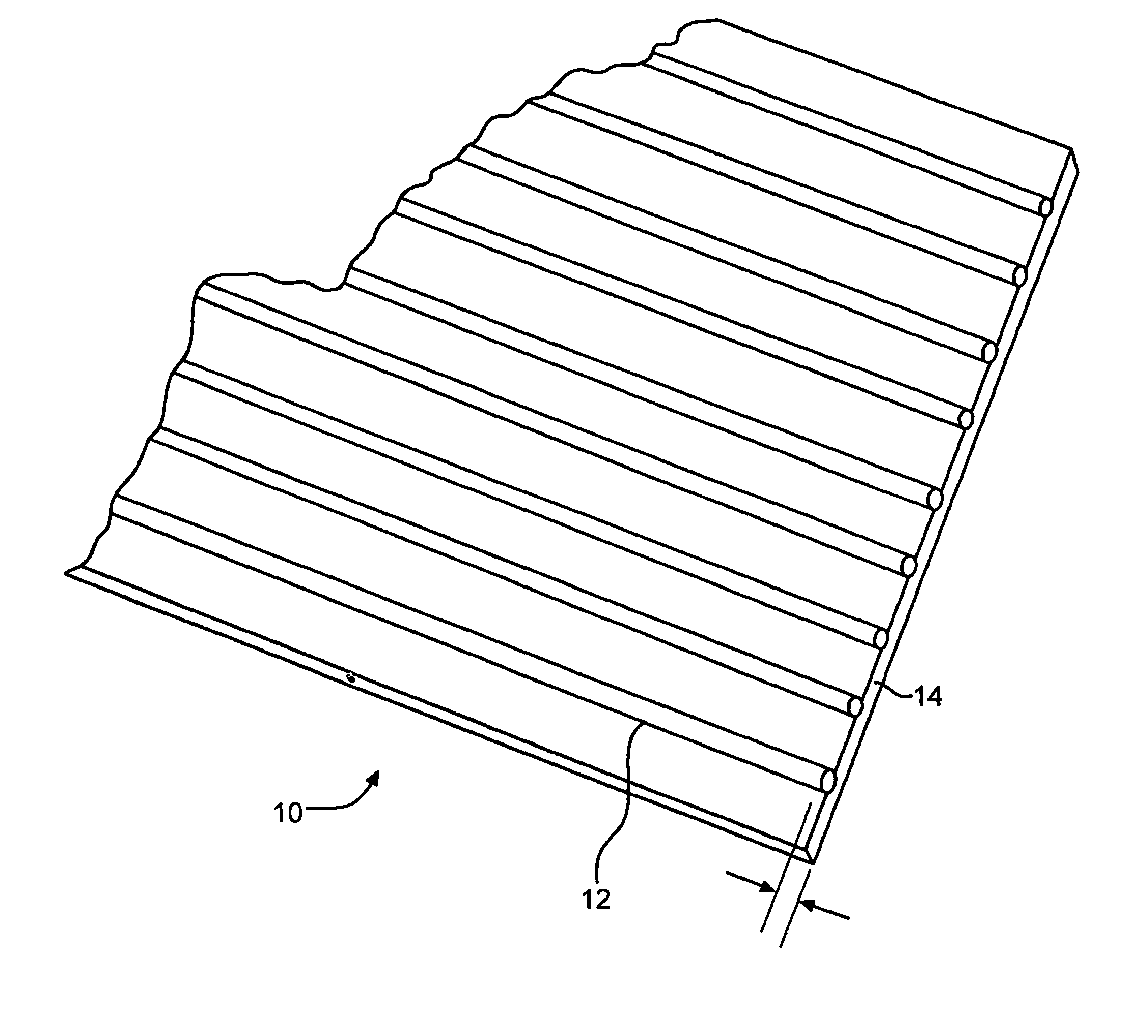
[0055]Thirty-three test batteries of type U2 (50 Ah) were made to illustrate how the present invention can be carried out on commercial battery making apparatus. Special absorbent separator / spacer material was prepared to produce these batteries. The separator / spacer spacer material was produced from an absorbent glass / synthetic fiber mat which had a surface area of 0.9 m2 / g, an average pore size of about 4 μm, a maximum pore size of about 25 μm, and contained 85% by weight of glass fibers and 15% by weight of organic fibers. The base material, which is commercially available from Hollingsworth & Vose Company under the designation “BG-089GB054”, had a basis weight of 89 grams per square meter and a thickness at 10 kPa of about 0.54 mm. The base material was subjected to a corrugating process which involved saturating it with a 5% by weight aqueous solution of sodium silicate and, while it was wet with the sodium silicate solution, passing it through a set of metallic corrugating rol...

example 2

[0064]Six Group 24 monopoly VRLA batteries were produced and filled with sulfuric acid containing 1 percent by weight of silica from unmilled, never dried precipitated silica slurry. The batteries contained absorptive all glass mat separator grade BG26067 available from Hollingsworth & Vose Company. The separator surfaces were in direct contact with the plates. The fibers of the separator had a surface area of 1.0 M2 / g,. The separator had an average pore size of about 4-6 μm, and a maximum pore size of about 25 μm The batteries were container formed without any difficulty. They were discharged at the 20-minute rate and averaged about 23 minutes of discharge time. Later, the batteries were discharged at the 5-hour rate and performed normally, delivering about 105 percent of their rated capacity, on average. One of the batteries was opened, and normally saturated separators were found inside, i.e., the separator material was saturated with liquid electrolyte. A layer of gel was formed...

example 3

[0066]Five factory produced Motive Power thirteen plate cells, capacity of 510 Ah (85 Ah per positive plate), were used in further investigation of the instant invention. The separator between the plates comprised of a layer of latex bonded 13 μm glass fiber veil having a nominal thickness of 0.38 mm adjacent to the positive plate, a spacer layer, nominal thickness 40 thousandths of an inch, of a polymeric netting that is available from Malted under the designation Malted 55-3757, positioned next to the veil, a layer of H&V Energy Guard ® BG 180GB117 glass / synthetic separator material, nominal thickness 1.17 mm, next to the netting, and a final spacer layer of Malted 55-3757 polymeric netting adjacent the negative plate.

[0067]Cell 1 was a control cell and was first used to determine the amount of electrolyte that would be absorbed by the separator and the active material in the cells. Cell 1 was filled with 5.35 liters of sulfuric acid having a specific gravity of 1.220. The unabsor...


PUM

PropertyMeasurementUnit
specific gravityaaaaaaaaaa

Abstract

A method for producing a lead acid battery that operates on the oxygen cycle is disclosed. The method includes the steps of: assembling a cell comprising a positive plate, a negative plate, and a sheet of separator material which is an absorbent, porous filtration medium, so that there is free space between the plates and surfaces of the separator, inserting the cell into a case, introducing into the case a mixture of sulfuric acid and silica including silica from a never dried precipitated silica slurry, causing the sulfuric acid in the mixture in the free space to gel, and sealing the case. The sulfuric acid in the mixture in the free space can be caused to gel by an increase in the silica content thereof, by an increase in the specific gravity thereof, or by both an increase in the silica content thereof, and an increase in the specific gravity thereof.

Description

BACKGROUND OF THE INVENTION[0001]1. Field of the Invention[0002]The invention relates to a new system for immobilizing electrolyte containing silica in lead acid batteries. This system relies on the use of silica particles from sources that have not been used in prior art electrolyte immobilizing systems and it also relies on the ability of separator materials and of the porous electrodes of the lead acid battery to filter silica particles from an electrolyte consisting of a mixture of sulfuric acid and silica particles. As a consequence of this filtering action there is a relative increase in the concentration of silica particles in the residual unfiltered electrolyte to levels at which gel formation occurs. In addition, gel formation can be caused to occur as a consequence of the increase in sulfate ion concentration in the electrolyte which occurs as the lead acid battery is being charged, either initially, after formation of positive and negative plates therein, or after use. Ch...

Claims


Application Information

Patent Timeline
Patent Type & Authority Patents(United States)
IPC IPC(8): H01M6/04H01M2/18H01MH01M2/16H01M10/00H01M10/04H01M10/08H01M10/10H01M10/12
CPCH01M10/10Y10T29/4911Y02E60/126H01M2300/0085Y02E60/10Y02P70/50H01M10/06H01M10/08
Inventor FERREIRA, ANTONIO L.ZGRUIS, GEORGE C.LIFSHUTZ, NORMAN
Owner HOLLINGSWORTH VOSE
Learn More